How to Set Up Airgap+ to Protect Your HBS Backups
Applicable Products
NAS
- All NAS models
- Operating systems:
- QTS 5.2.x and later
- QuTS hero h5.2.x and later
- Applications: Hybrid Backup Sync (HBS3) 25 and later
Routers
- QHora-321
- QHora-322
- Operating system: QuRouter 2.4.2 and later
Switches
- QSW-M3216R-8S8T
- QSW-M3212R-8S4T
- QSW-M3224-24T
- QSW-M7308R-4X
- Operating systems:
- QSS 4.3 and later
- QSS Pro 4.3 and later
Introduction
Airgap+ is QNAP's solution to creating offline backups for enterprise-level data protection.
By connecting your QNAP NAS devices to a QNAP router or switch that supports Airgap+, you can create a private network where the router/switch only allows connections between the NAS devices when HBS (Hybrid Backup Sync) is running a backup or sync job. The router or switch rejects all other connection requests to the backup NAS at other times, isolating and safeguarding your backup data.
This tutorial provides a step-by-step guide for setting up an Airgap+ environment for your HBS backups.
Airgap+ Options and Requirements
| Standard Airgap+ | Advanced Airgap+ | |
|---|---|---|
| QNAP Router |
| |
| QNAP Switch |
| |
| QNAP NAS Operating System |
| |
| QNAP NAS Application | HBS 3 (Hybrid Backup Sync) version 25 or later | |
| QNAP NAS Devices | At least two NAS devices:
| At least three NAS devices:
|
| ||
| Airgap Restriction | The router or switch only allows connections in the following situations: | |
| The source NAS is transferring data to the backup NAS via HBS. | The bridge NAS is transferring data from the source NAS or to the backup NAS via HBS. | |
| Advantages |
|
|
You can deploy Airgap+ using either a router-based or switch-based setup, depending on the network device you have and how you prefer to build your airgapped network. Airgap+ functions most reliably when all NAS devices use static IP addresses, regardless of which setup you choose.
- Router-based setups: Routers support DHCP reservation, which helps keep IP assignments consistent. Using this feature reduces the chances of communication issues during Airgap+ operations.
- Switch-based setups: Switches do not support IP reservation, even when they include a DHCP server. This can cause inconsistent IP assignments, which may interrupt Airgap+ communication. If you use a switch-based setup, it is strongly recommended to configure static IP addresses on all NAS devices to maintain stable connectivity during HBS jobs.
Setting Up Airgap+ with a Router-Based Network
Standard Airgap+
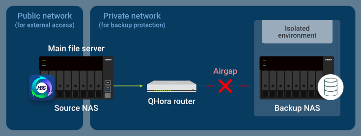
In the standard Airgap+ setup, the source and backup NAS devices are connected to the same Airgap+ router. While the source NAS is connected to a public network, it is also in a private network with the backup NAS through the router.
In this private network, the router only allows the source NAS to access the backup NAS when the source NAS is running an HBS job.
How standard Airgap+ works
Normally, only the source NAS has access to the router. The backup NAS is completely isolated.
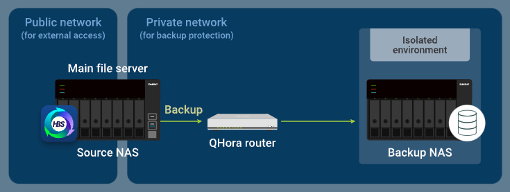
When the source NAS runs a backup job in HBS, the router allows data to be transferred from the source NAS to the backup NAS.
Standard Airgap+ Setup Instructions
To set up a standard Airgap+ environment, you need to configure the Airgap+ router and both NAS devices before you can create HBS jobs to start backing up your data.
A. Configure the router
- Connect the source NAS and the backup NAS directly to the Airgap+ router to create a private network.Important
We highly recommend configuring a static IP address for the backup NAS. This ensures the Airgap+ settings on all devices remain valid over time.
- To configure a static IP address for the backup NAS network adapter that is connected to the router, see one of the following:
- "Configuring IPv4 settings" in the QTS User Guide or QuTS hero User Guide
- "Configuring IPv6 settings" in the QTS User Guide or QuTS hero User Guide
- If you choose to use a DHCP server to assign IP addresses, make sure to reserve the backup NAS IP address on the router LAN port that is connected to the backup NAS.
For configuration details, see "Configuring local area network (LAN) interface settings" ("Reserved IP Table" setting) in the QuRouter for QHora Routers User Guide.
- To configure a static IP address for the backup NAS network adapter that is connected to the router, see one of the following:
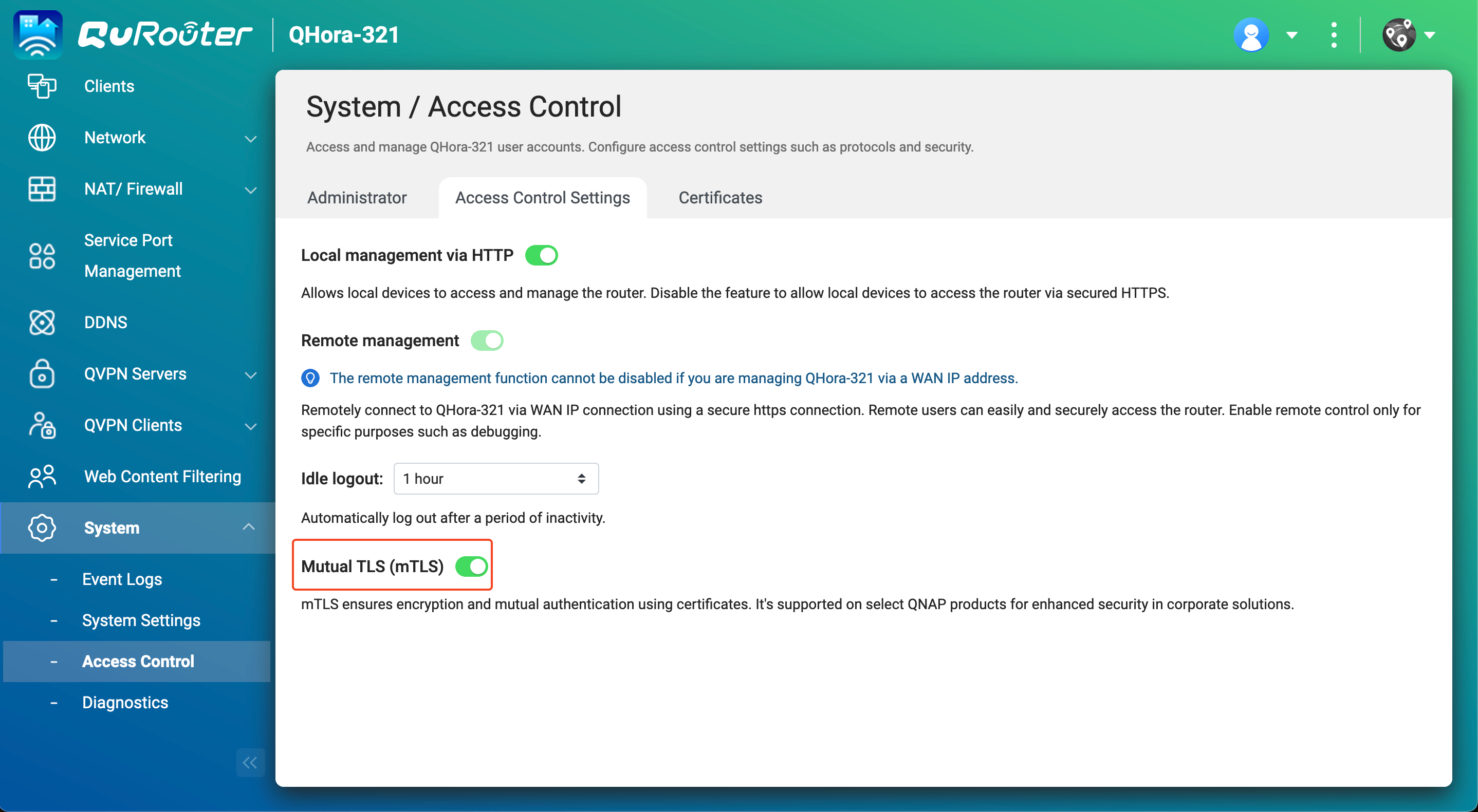
- Enable mutual TLS connection on the router.
- Log in to the router operating system, QuRouter.
- Go to System > Access Control > Access Control Settings.
- Enable Mutual TLS (mTLS).

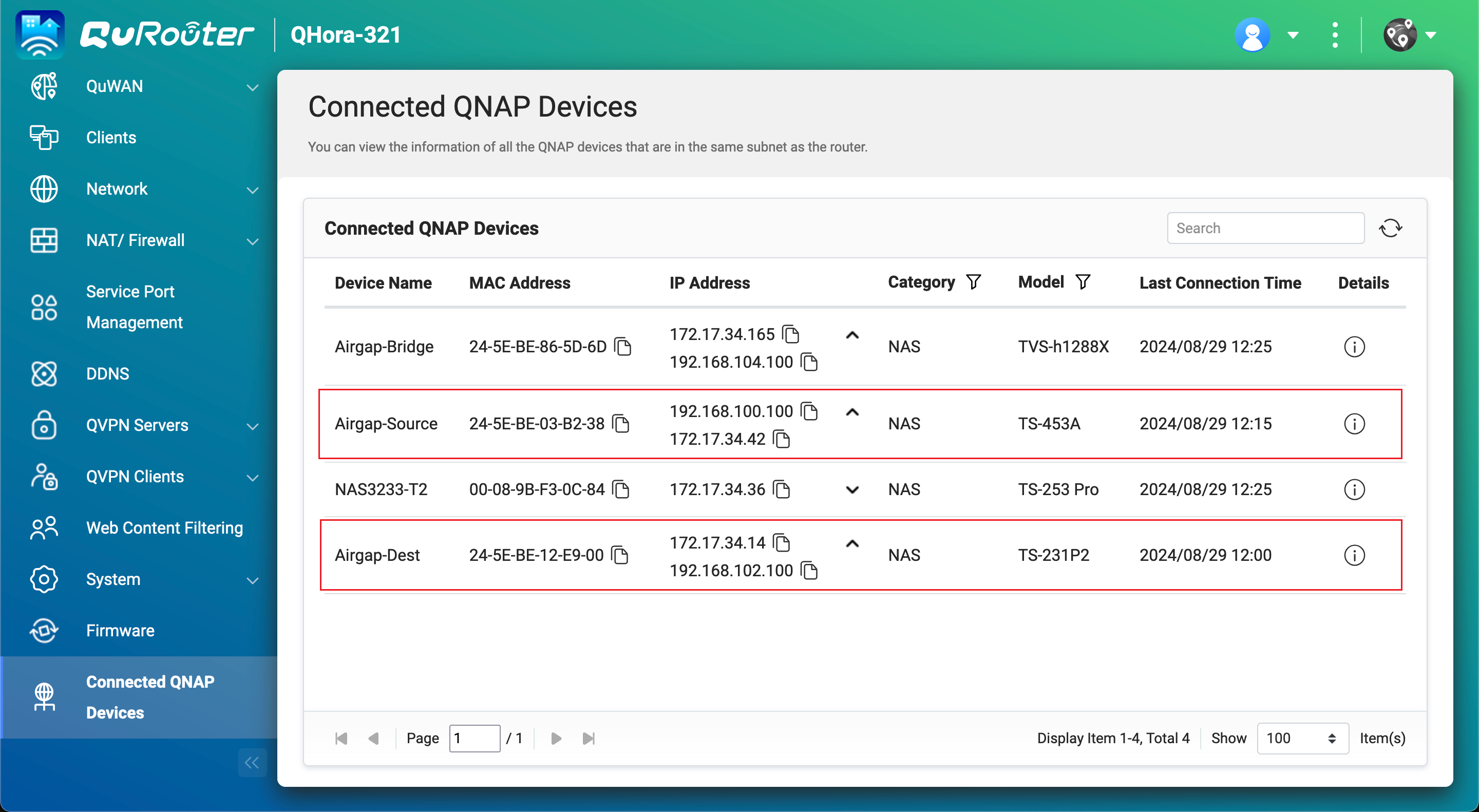
- Obtain the IP address of your backup NAS in the private network.
- In QuRouter, go to Connected QNAP Devices.
- Identify the backup NAS device.
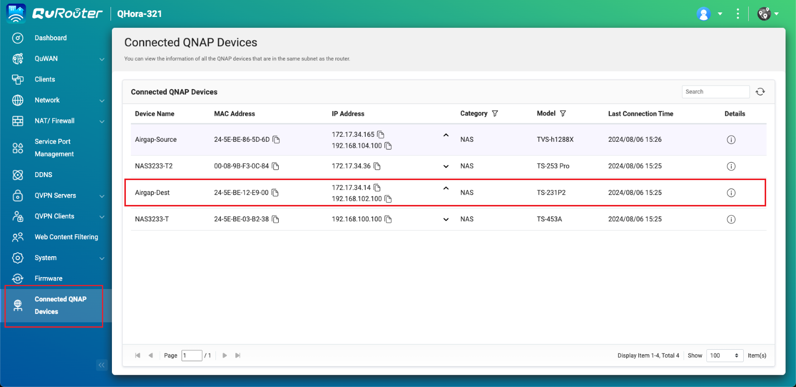
- Copy the backup NAS IP address.Note
- The NAS may have more than one IP address listed. Copy the IP address that is in the same IP range as the router.
In our example, the IP address is192.168.102.100. - Use this IP address in steps B-2c and D-1e.
- The NAS may have more than one IP address listed. Copy the IP address that is in the same IP range as the router.
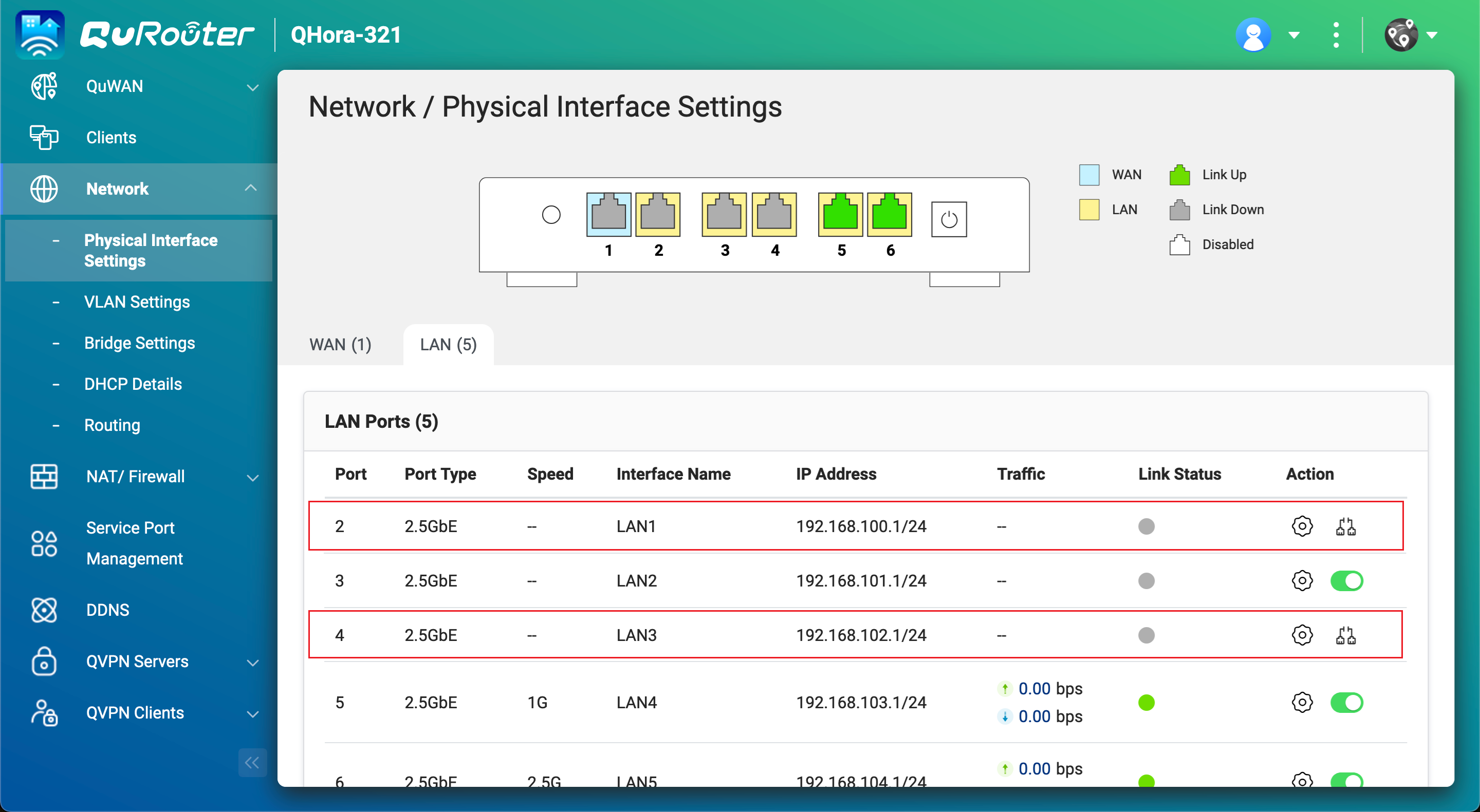
- Obtain the LAN port IP address on the Airgap+ router that is connected to the backup NAS.
- In QuRouter, go to Network > Physical Interface Settings > LAN.
- Identify the router LAN port that is connected to the backup NAS.
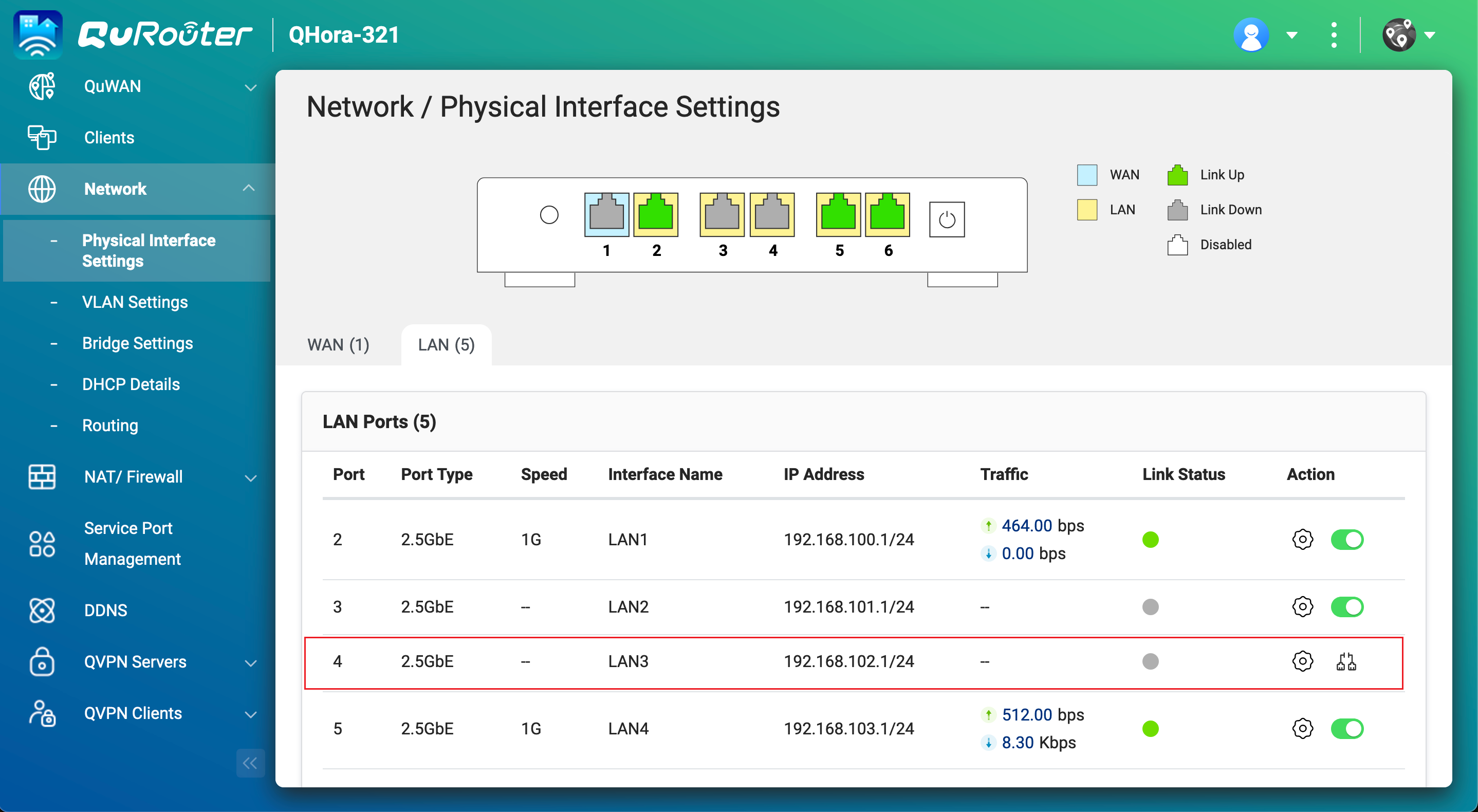
- Under IP Address, copy the IP address.NoteUse the last octet of the IP address in step B-2e.
In our example, the last octet of the IP address192.168.102.1is1. - Under IP Address, copy the subnet mask.NoteSpecify this subnet mask in step B-2d.
In our example, the subnet mask is/24.
B. Configure the source NAS
- Identify the source NAS adapter that is connected to the Airgap+ router.
- On the source NAS, open Network & Virtual Switch.
- Go to Network > Interfaces.
- Identify the adapter that is connected to the Airgap+ router.NoteUse this adapter in step B-2f.
In our example, adapter 2 is connected to the Airgap+ router.
- Copy the IP address of the adapter.NoteUse the first three octets in the IP address in step B-2e.
In our example, the first three octets of the IP address192.168.100.100are192.168.100.
- Create a static route rule on the source NAS for connecting to the backup NAS.
- In Network & Virtual Switch, go to Network > Route.
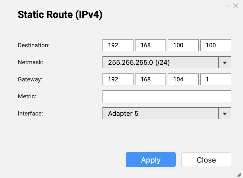
- Under Static Route, click Add.
The Static Route (IPv4) window opens. - Next to Destination, specify the IP address of the backup NAS (see step A-3c).
- Next to Netmask, specify the subnet mask for the router LAN port that is connected to the backup NAS (see step A-4d).
- Next to Gateway, specify the first three octets of the IP address for the source NAS adapter that is connected to the router (see step B-1d), followed by the last octet of the IP address for the router LAN port that is connected to the backup NAS (see step A-4c).NoteIn our example:
- Step B-1d provides the first three octets of the IP address (
192.168.100). - Step A-4c provides the last octet of the IP address (
1).
192.168.100.1. Enter this address in the Gateway field.
Also use this address in step D-1j. - Step B-1d provides the first three octets of the IP address (
- Next to Interface, select the source NAS adapter that is connected to the router (see step B-1c).

- Click Apply.
Network & Virtual Switch adds the static route rule.
C. Configure the backup NAS
- On the backup NAS, enable the RTRR server.
This allows HBS jobs on the source NAS to use the backup NAS as a backup destination.- On the backup NAS, open HBS.
- Go to Services > Remote NAS (RTRR Server).
- Next to Status, click the toggle button to enable the RTRR server.
- Configure the RTRR server settings.
For details, see Configuring the RTRR server.Note- Copy the port number specified on this page and enter it in step D-1f.
- Remember the account access method and credentials configured here and use them in steps D-1g and D-1h.
- Click Apply.
HBS enables the RTRR server with the configured settings.
D. Create an HBS job on the source NAS
- In HBS on the source NAS, create a storage space for the backup NAS.
This allows you to save the connection settings of the backup NAS and enable an Airgap+ connection between the source NAS and the backup NAS.- On the source NAS, open HBS.
- Go to Storage Spaces.
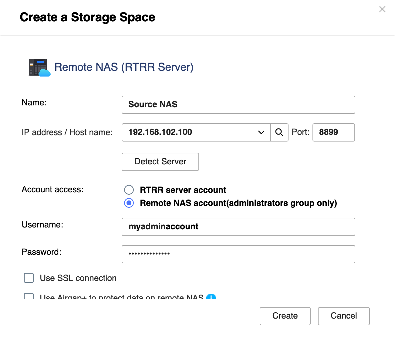
- Click Create, and then click Remote NAS.
The Create a Storage Space window opens. - Enter a name to identify the backup NAS.
- Enter the backup NAS IP address (see step A-3c).
- Enter the backup NAS RTRR server port number (see step C-1d).
- Select an account access method you configured in the RTRR server settings on the backup NAS (see step C-1d).
- Enter the credentials for the account access method (see step C-1d).
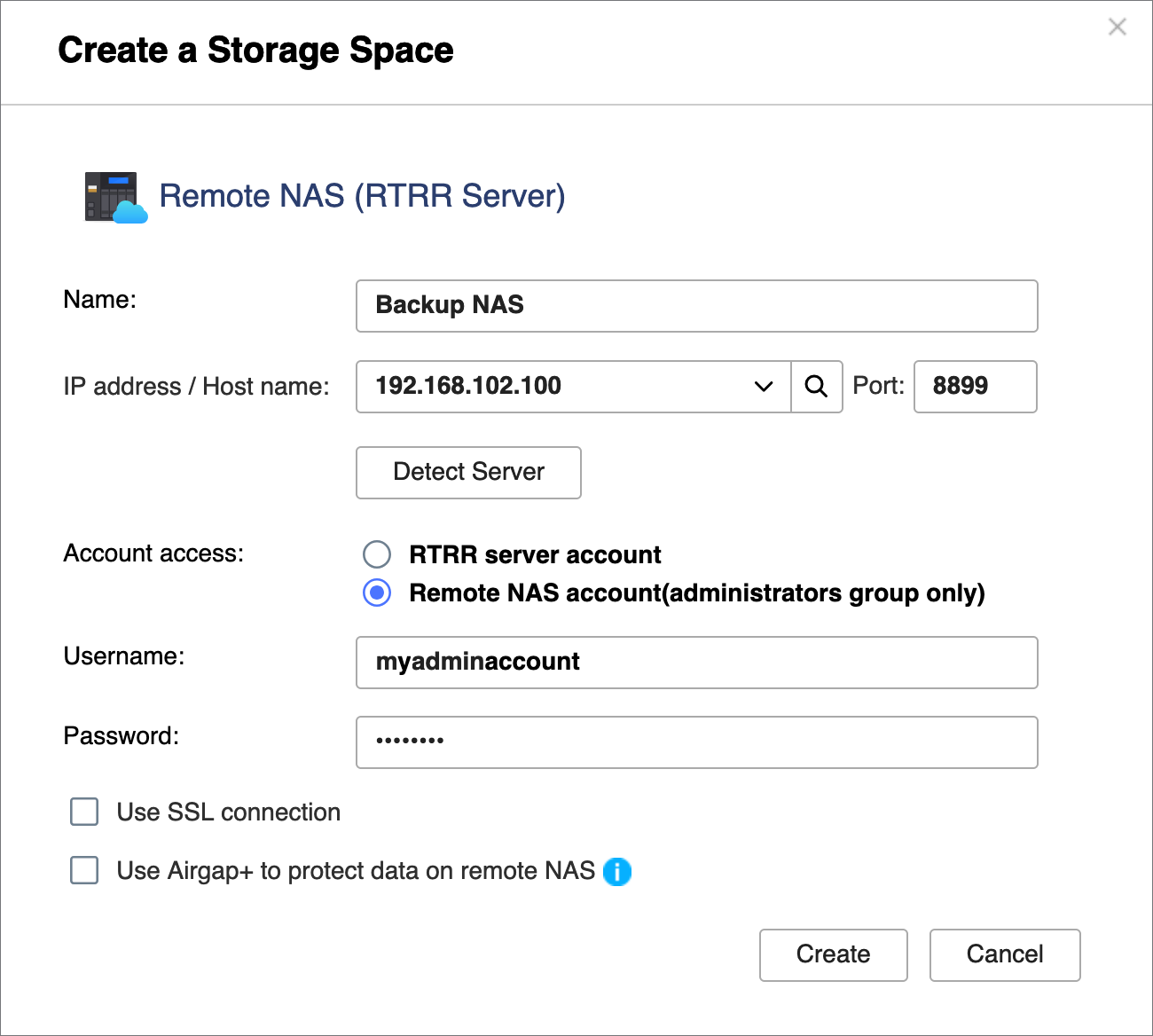
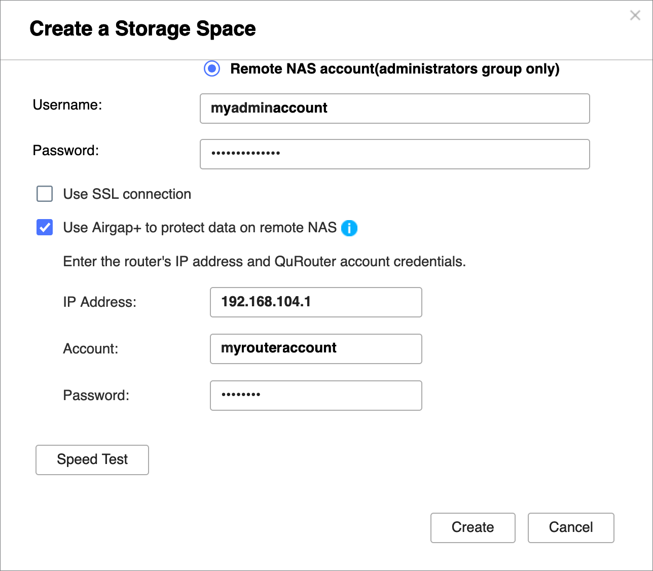
- Select Use Airgap+ to protect data on remote NAS.
- Select Router as the Airgap+ device.
- Enter the gateway IP address from the static route rule you created (see step B-2e).
- Enter the port number.
- Enter the router management account credentials.
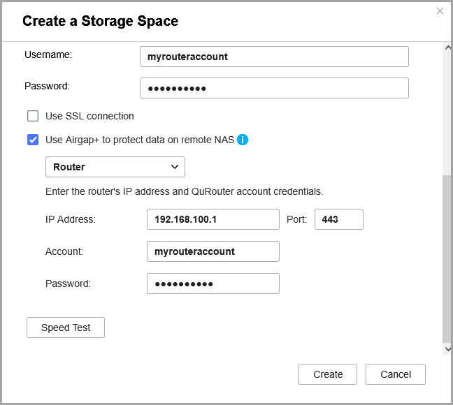
- Click Create.
HBS creates the storage space and adds it to the storage space list.
You should see "Protected by Airgap+" at the top of the storage space entry.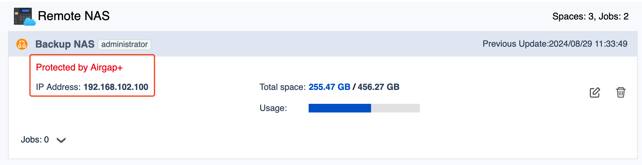
- Create a backup job on the source NAS.
- In HBS, go to Backup & Restore.
- Click Backup Now and then click New backup job.
- Follow the steps in the wizard.
For details, see Creating a backup job.
- After the backup job is created, verify that the Airgap+ link has been established on the router.
- In QuRouter, go to Network > Physical Interface Settings > LAN.
- Identify the LAN port that is connected to the backup NAS.
- Under Link Status, verify there is an Airgap+ tag for the LAN port.

You can now run the Airgap+ protected HBS backup job on the source NAS.
Advanced Airgap+
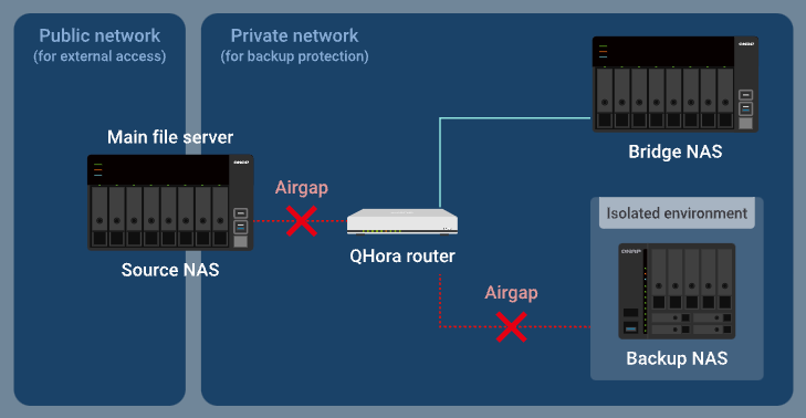
In the advanced Airgap+ setup, the source, backup, and bridge NAS devices are connected to the same router. While the source NAS is connected to a public network, it is also in a private network with the backup and bridge NAS devices through the router.
In this private network, the router only allows the bridge NAS to access the source and backup NAS devices when the bridge NAS is running an HBS job.
Because the bridge NAS runs all the HBS jobs, the source NAS can conserve and allocate more system resources for other important tasks and services.
How advanced Airgap+ works
Normally, only the bridge NAS has access to the router. The backup NAS is completely isolated.
When the bridge NAS runs an active sync job in HBS, the router allows the data you want to back up to be transferred from the source NAS through the router to the bridge NAS, while the backup NAS remains isolated.
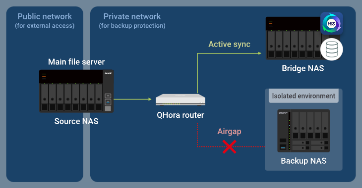
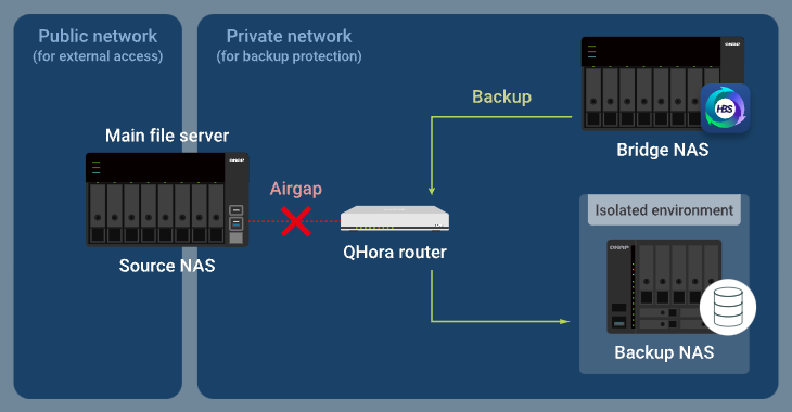
After completing the active sync job, the bridge NAS then runs a backup job, and the router allows the backup data to be transferred from the bridge NAS through the router to the backup NAS, while the source NAS is blocked from accessing the private network.
Advanced Airgap+ Setup Instructions
To set up an advanced Airgap+ environment, you need to configure the Airgap+ router and all the NAS devices before you can create HBS jobs to start backing up your data.
A. Configure the router
- Connect the source, bridge, and backup NAS devices directly to the Airgap+ router to create a private network.Important
We highly recommend configuring static IP addresses for the source and backup NAS devices. This ensures the Airgap+ settings on all devices remain valid over time.
- To configure static IP addresses for the backup and source NAS network adapters that are connected to the router, see one of the following:
- "Configuring IPv4 settings" in the QTS User Guide or QuTS hero User Guide
- "Configuring IPv6 settings" in the QTS User Guide or QuTS hero User Guide
- If you choose to use a DHCP server to assign IP addresses, make sure to reserve the backup and source NAS IP addresses on the router LAN ports that are connected to the NAS devices.
For configuration details, see "Configuring local area network (LAN) interface settings" ("Reserved IP Table" setting) in the QuRouter for QHora Routers User Guide.
- To configure static IP addresses for the backup and source NAS network adapters that are connected to the router, see one of the following:
- Enable mutual TLS connection on the router.
- Log in to the router operating system, QuRouter.
- Go to System > Access Control > Access Control Settings.
- Enable Mutual TLS (mTLS).
- Obtain the IP addresses of your source and backup NAS devices in the private network.
- In QuRouter, go to Connected QNAP Devices.
- Identify the source and backup NAS devices.
- Copy the source NAS IP address.Note
- The NAS may have more than one IP address listed. Copy the IP address that is in the same IP range as the router.
In our example, the IP address is192.168.100.100. - Use this IP address in steps B-2c and D-1e.
- The NAS may have more than one IP address listed. Copy the IP address that is in the same IP range as the router.
- Copy the backup NAS IP address.Note
- The NAS may have more than one IP address listed. Copy the IP address that is in the same IP range as the router.
In our example, the IP address is192.168.102.100. - Use this IP address in steps B-3c and D-2e.
- The NAS may have more than one IP address listed. Copy the IP address that is in the same IP range as the router.
- Obtain the LAN port IP addresses on the Airgap+ router that are connected to the source and backup NAS devices.
- In QuRouter, go to Network > Physical Interface Settings > LAN.
- Identify the LAN ports on the router that are connected to the source and backup NAS devices.
- Under IP Address, copy the IP address for the LAN port connected to the source NAS.NoteUse the last octet of the IP address in step B-2e.
In our example, the last octet of the IP address192.168.100.1is1. - Copy the subnet mask for the LAN port connected to the source NAS.NoteSpecify the subnet mask in step B-2d.
In our example, the subnet mask is/24. - Copy the IP address for the LAN port connected to the backup NAS.NoteUse the last octet of the IP address in step B-3e.
In our example, the last octet of the IP address192.168.102.1is1. - Copy the subnet mask for the LAN port connected to the backup NAS.NoteSpecify the subnet mask in step B-3d.
In our example, the subnet mask is/24.
B. Configure the bridge NAS
- Identify the bridge NAS adapter that is connected to the Airgap+ router.
- On the bridge NAS, open Network & Virtual Switch.
- Go to Network > Interfaces.
- Identify the adapter that is connected to the Airgap+ router.NoteUse this adapter in steps B-2f and B-3f.
In our example, adapter 5 is connected to the Airgap+ router.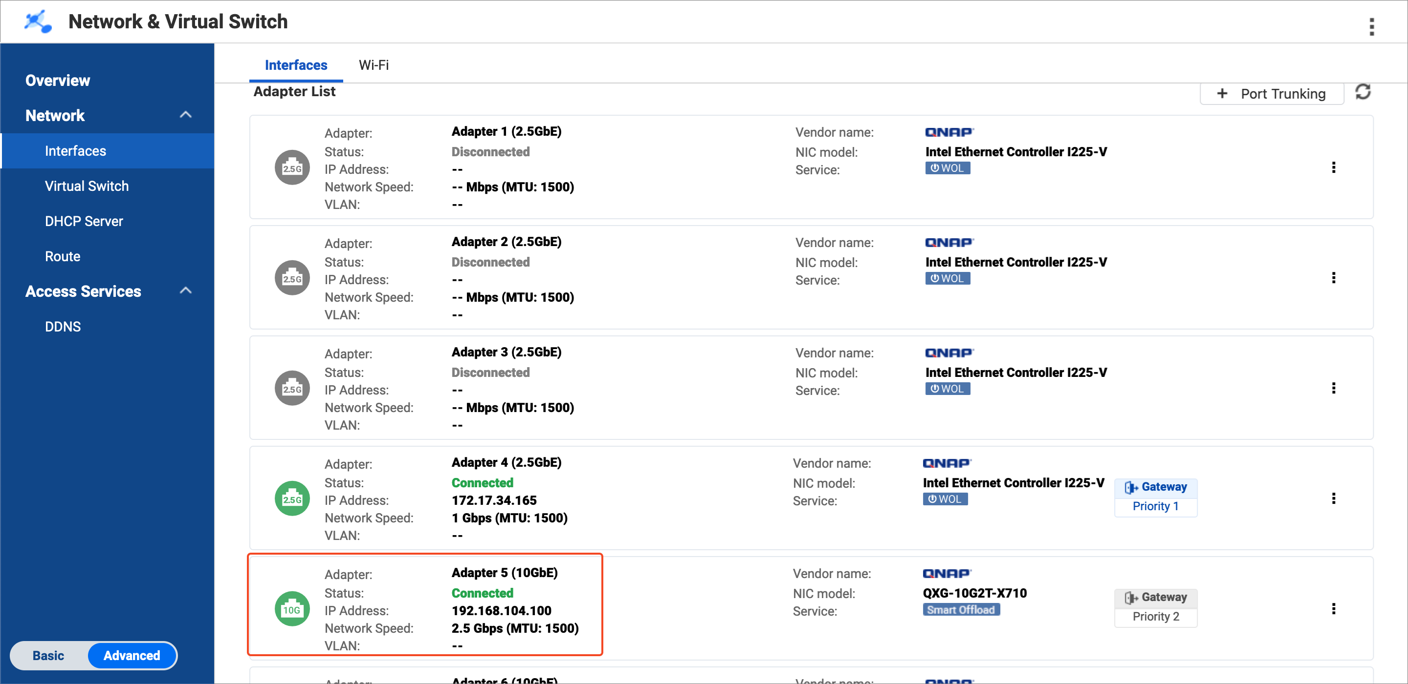
- Copy the IP address of the adapter.NoteUse the first three octets of the IP address in steps B-2e and B-3e.
In our example, the first three octets of the IP address192.168.104.100are192.168.104.
- Create a static route rule on the bridge NAS for connecting to the source NAS.
- On the bridge NAS, go to Network & Virtual Switch > Network > Route.
- Under Static Route, click Add.
The Static Route (IPv4) window opens. - Next to Destination, specify the IP address of the source NAS (see step A-3c).
- Next to Netmask, specify the subnet mask of the router LAN port that is connected to the source NAS (see step A-4d).
- Next to Gateway, specify the first three octets of the IP address for the bridge NAS adapter that is connected to the router (see step B-1d), followed by the last octet of the IP address for the router LAN port that is connected to the source NAS (see step A-4c).NoteIn our example:
- Step B-1d provides the first three octets of the IP address (
192.168.104). - Step A-4c provides the last octet of the IP address (
1).
Join the two to obtain
192.168.104.1. Enter this address in the Gateway field.
Also use this address in step D-1j. - Step B-1d provides the first three octets of the IP address (
- Next to Interface, select the bridge NAS adapter that is connected to the router (see step B-1c).
- Click Apply.
Network & Virtual Switch adds the static route rule.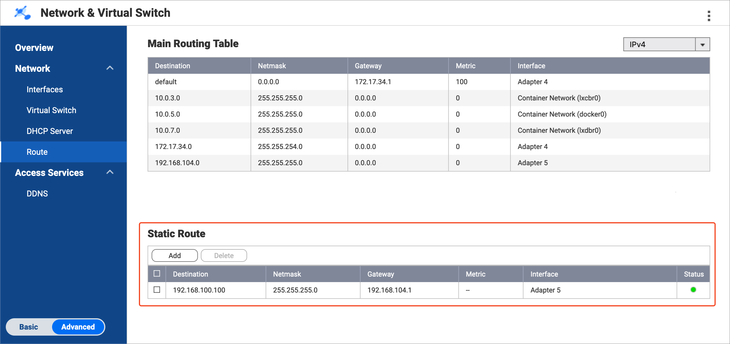
- Create a static route rule on the bridge NAS for connecting to the backup NAS.
- On the bridge NAS, remain in Network & Virtual Switch > Network > Route.
- Under Static Route, click Add.
The Static Route (IPv4) window opens. - Next to Destination, specify the IP address of the backup NAS (see step A-3d).
- Next to Netmask, specify the subnet mask of the router LAN port that is connected to the backup NAS (see step A-4f).
- Next to Gateway, specify the first three octets of the IP address for the bridge NAS adapter that is connected to the router (see step B-1d), followed by the last octet of the IP address for the router LAN port that is connected to the backup NAS (see step A-4e).NoteIn our example:
- Step B-1d provides the first three octets of the IP address (
192.168.104). - Step A-4e provides the last octet of the IP address (
1).
Join the two to obtain
192.168.104.1. Enter this address in the Gateway field.
Also use this address in step D-2j. - Step B-1d provides the first three octets of the IP address (
- Next to Interface, select the bridge NAS adapter that is connected to the router (see step B-1c).

- Click Apply.
Network & Virtual Switch adds the static route rule.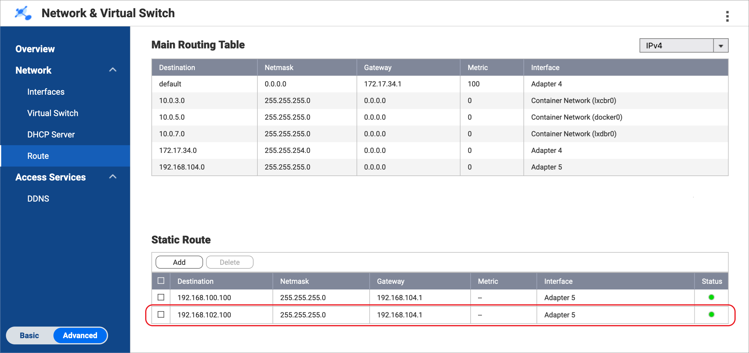
C. Configure the source and backup NAS devices
- Enable the RTRR server on the source NAS.
This allows HBS jobs on the bridge NAS to use the source NAS as a sync source.- On the source NAS, open HBS.
- Go to Services > Remote NAS (RTRR Server).
- Next to Status, click the toggle button to enable the RTRR server.
- Configure the RTRR server settings.
For details, see Configuring the RTRR server.Note- Copy the port number specified on this page and enter it in step D-1f.
- Remember the account access method and credentials configured here and use them in steps D-1g and D-1h.
- Click Apply.
HBS enables the RTRR server on the source NAS.
- Enable the RTRR server on the backup NAS.
This allows HBS jobs on the bridge NAS to use the backup NAS as a backup destination.- On the backup NAS, open HBS.
- Go to Services > Remote NAS (RTRR Server).
- Next to Status, click the toggle button to enable the RTRR server.
- Configure the RTRR server settings.
For details, see Configuring the RTRR server.Note- Copy the port number specified on this page and enter it in step D-2f.
- Remember the account access method and credentials configured here and use them in steps D-2g and D-2h.
- Click Apply.
HBS enables the RTRR server on the backup NAS.
D. Create HBS jobs on the bridge NAS
- In HBS on the bridge NAS, create a storage space for the source NAS.
This allows you to save the connection settings of the source NAS and enable an Airgap+ connection between the source NAS and the bridge NAS.- On the bridge NAS, open HBS.
- Go to Storage Spaces.
- Click Create, and then click Remote NAS.
The Create a Storage Space window opens. - Enter a name to identify the source NAS.
- Enter the source NAS IP address (see step A-3c).
- Enter the source NAS RTRR server port number (see step C-1d).
- Select an account access method you configured in the RTRR server settings on the source NAS (see step C-1d).
- Enter the credentials for the account access method (see step C-1d).

- Select Use Airgap+ to protect data on remote NAS.
- Select Router as the Airgap+ device.
- Enter the gateway IP address from the static route rule on the bridge NAS for connecting to the source NAS (see step B-2e).
- Enter the port number.
- Enter the router management account credentials.
- Click Create.
HBS creates the storage space and adds it to the storage space list.
- In HBS on the bridge NAS, create a storage space for the backup NAS.
This allows you to save the connection settings of the backup NAS and enable an Airgap+ connection between the bridge NAS and the backup NAS.- On the bridge NAS, stay in HBS.
- Go to Storage Spaces.
- Click Create, and then click Remote NAS.
The Create a Storage Space window opens. - Enter a name to identify the backup NAS.
- Enter the backup NAS IP address (see step A-3d).
- Enter the backup NAS RTRR server port number (see step C-2d).
- Select an account access method you configured in the RTRR server settings on the backup NAS (see step C-2d).
- Enter the credentials for the account access method (see step C-2d).
- Select Use Airgap+ to protect data on remote NAS.
- Enter the gateway IP address from the static route rule on the bridge NAS for connecting to the backup NAS (see step B-3e).
- Enter the router management account credentials.
- Click Create.
HBS creates the storage space and adds it to the storage space list.
After both storage spaces are created, you should see "Protected by Airgap+" at the top of the storage space entries in HBS > Storage Spaces.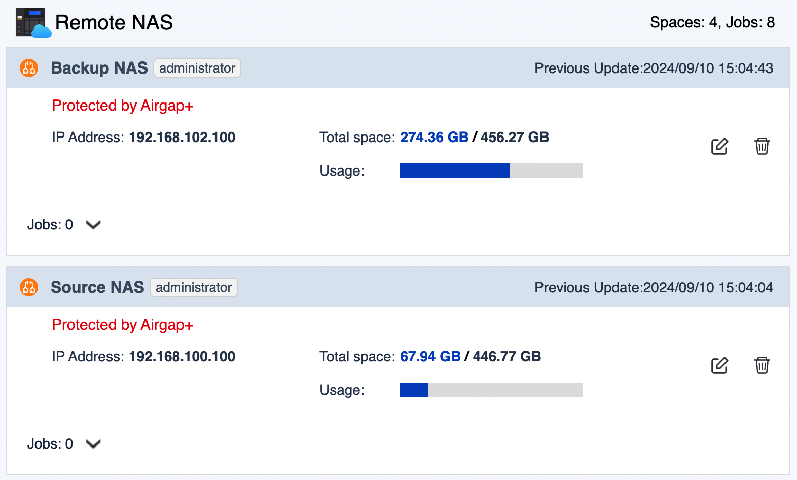
- Create an active sync job on the bridge NAS to transfer backup data from the source NAS to the bridge NAS.
- On the bridge NAS, go to HBS > Sync.
- Click Sync Now and then click Active Sync Job.
- Follow the steps in the wizard.
For details, see Creating an active sync job.
- Create a backup job on the bridge NAS to transfer the backup data to the backup NAS.
- On the bridge NAS, go to HBS > Backup & Restore.
- Click Backup Now and then click New backup job.
- Follow the wizard to select the source and destination folders.ImportantMake sure the source folder in this backup job is the same as the destination folder in the active sync job you just created.
- On the Schedule page, select Run after job, and then select the active sync job you just created.
This allows the backup job to automatically run every time the active sync job finishes, completing the backup data transfer to your backup NAS.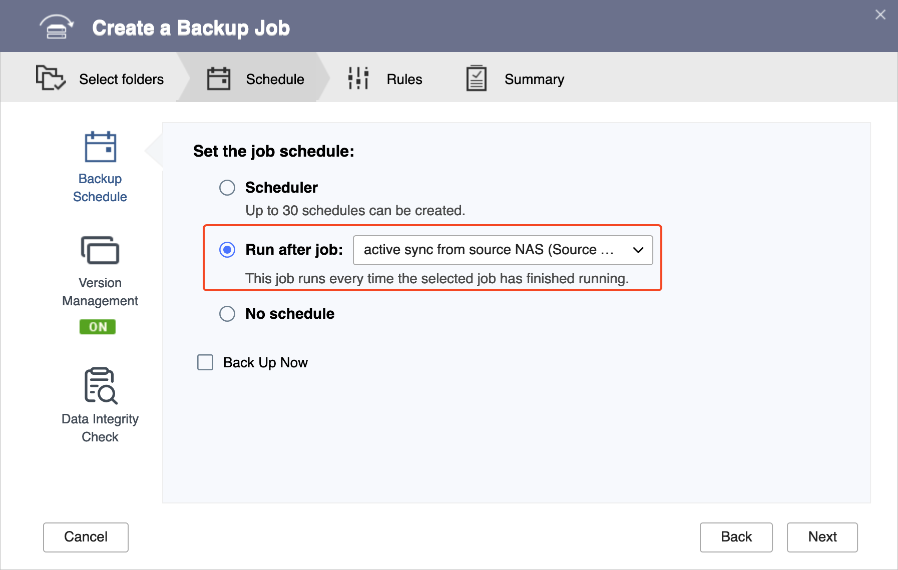
- Follow the remaining steps in the wizard.
For details, see Creating a backup job.
- After the active sync job and backup job are created, verify that the Airgap+ links have been established on the router.
- On the router, go to QuRouter > Network > Physical Interface Settings > LAN.
- Identify the LAN ports that are connected to the source and backup NAS devices.
- Under Link Status, verify there are Airgap+ tags for the LAN ports.

You can now run the HBS active sync job on the bridge NAS to transfer the data you want to back up.
After the active sync job finishes transferring the backup data from the source NAS to the bridge NAS, the backup job will automatically run and transfer the backup data from the bridge NAS to its final destination, the backup NAS. The entire process is now protected by Airgap+.
Setting Up Airgap+ with a Switch-Based Network
Standard Airgap+
In a switch-based Airgap+ setup, both the source NAS and the backup NAS connect to the same isolated switch. The source NAS also maintains a connection to the public network, but the backup NAS stays inside the private network created through the switch.
Within this isolated network segment, the switch permits communication from the source NAS to the backup NAS only during an active HBS backup task, preventing any other access outside of the scheduled job.
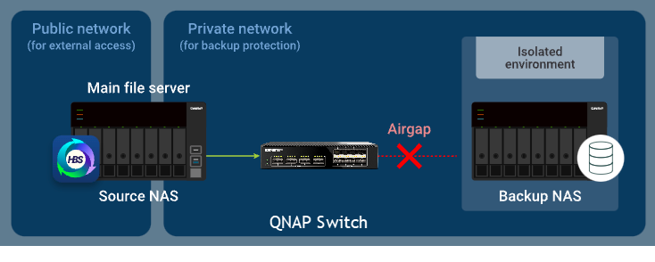
How standard Airgap+ works
Under normal conditions, only the source NAS has network access beyond the switch. The backup NAS remains fully isolated within the private network segment.
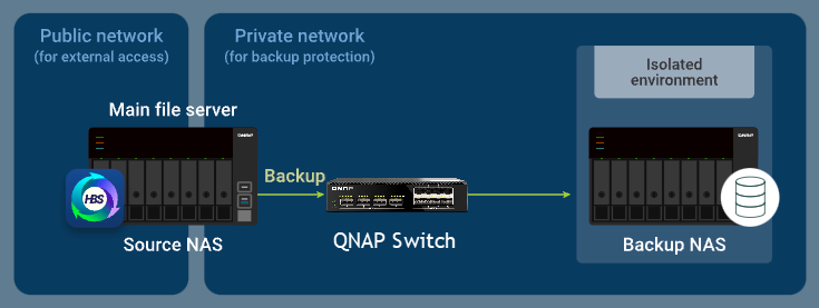
When the source NAS starts an HBS backup task, the switch temporarily enables traffic between the two NAS devices, allowing data to flow from the source NAS to the backup NAS for the duration of the job.
Standard Airgap+ Setup Instructions
To configure a standard Airgap+ environment using a switch, you must set up the Airgap+ switch and both NAS devices before creating HBS backup jobs.
A. Configure the switch
- Connect the source NAS and the backup NAS directly to the Airgap+ switch to create a private network.Important
It is recommended to configure a static IP address for the backup NAS to ensure that the Airgap+ settings on all devices remain valid over time.
To configure a static IP address for the backup NAS network adapter that is connected to the switch, see one of the following:
- "Configuring IPv4 settings" in the QTS User Guide or QuTS hero User Guide
- "Configuring IPv6 settings" in the QTS User Guide or QuTS hero User Guide
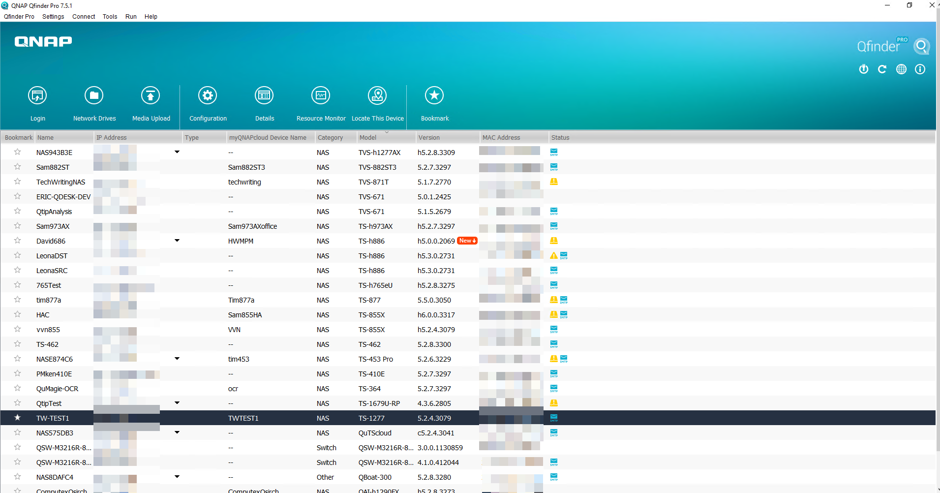
- Obtain the IP address of your backup NAS in the private network.
- Open Qfinder Pro.
- Identify the backup NAS device.
- Copy the backup NAS IP address.
 Note
Note- The NAS may have more than one IP address listed. Copy the IP address that is in the same IP range as the switch.
In our example, the IP address is192.168.102.100. - Use this IP address in steps B-2c and D-1e.
- The NAS may have more than one IP address listed. Copy the IP address that is in the same IP range as the switch.
- Obtain the LAN port IP address on the Airgap+ switch that is connected to the backup NAS.
- Log in to QSS or QSS Pro.
- Go to System > IP Configuration > IPv4 Interface Settings.
- Under IP Address, identify the IPv4 address of the network adapter that is connected to the NAS.
- Copy the switch LAN port IP address.NoteUse the last octet of this IP address in step B-2e. If the IP address is 192.168.102.1, the last octet of the IP address is 1.
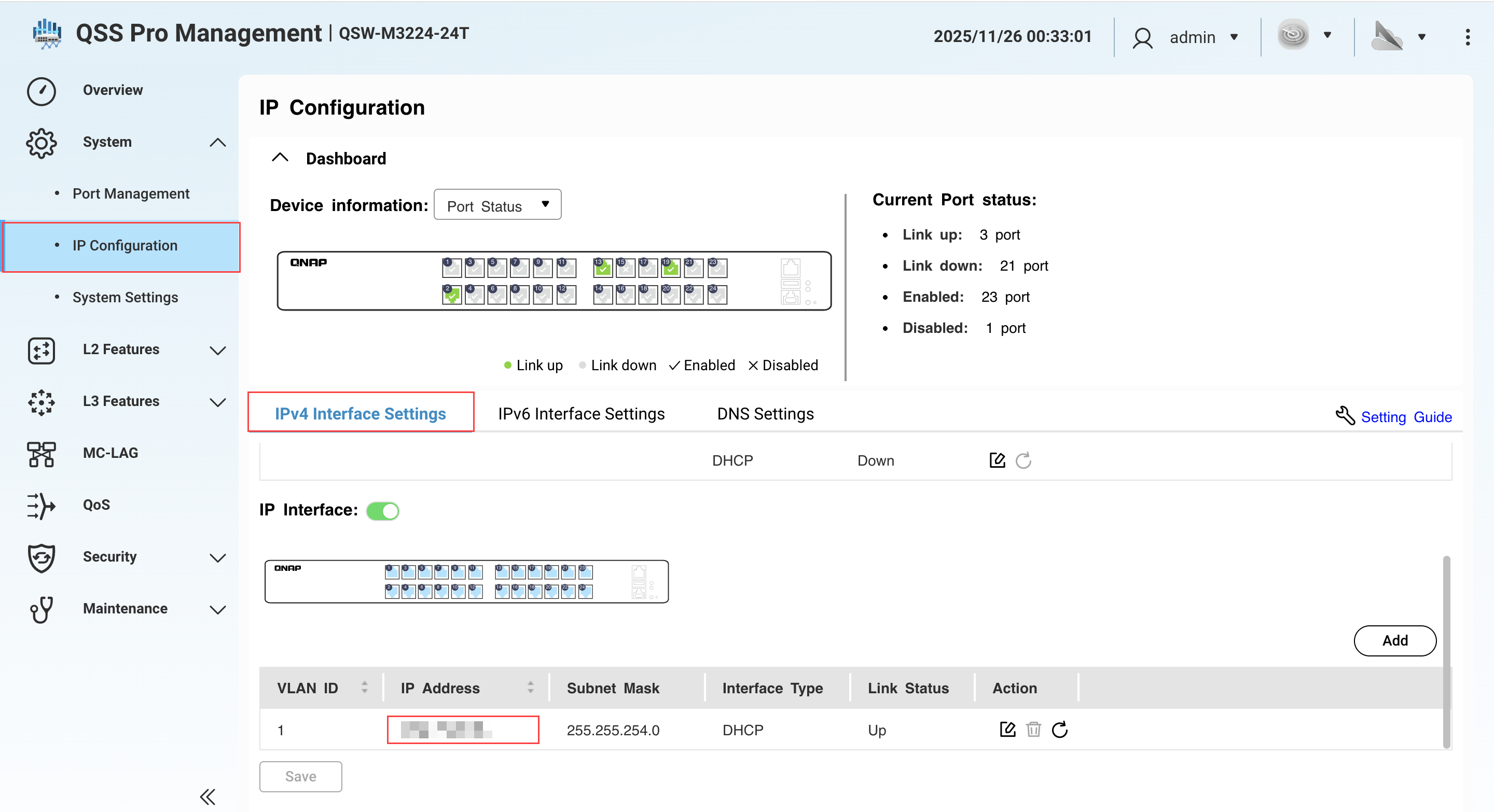
- Under Subnet Mask, copy the subnet mask.NoteSpecify this subnet mask in step B-2d. In our example, the subnet mask is
/24.
B. Configure the source NAS
- Identify the source NAS adapter that is connected to the Airgap+ switch.
- On the source NAS, open Network & Virtual Switch.
- Go to Network > Interfaces.
- Identify the adapter that is connected to the Airgap+ switch.NoteUse this adapter in step B-2f.
In our example, adapter 2 is connected to the Airgap+ switch. - Copy the IP address of the adapter.NoteUse the first three octets in the IP address in step B-2e.
In our example, the first three octets of the IP address192.168.100.100are192.168.100.
- Create a static route rule on the source NAS for connecting to the backup NAS.
- In Network & Virtual Switch, go to Network > Route.
- Under Static Route, click Add.
The Static Route (IPv4) window opens. - Next to Destination, specify the IP address of the backup NAS (see step A-2c).
- Next to Netmask, specify the subnet mask for the switch LAN port that is connected to the backup NAS (see step A-3e).
- Next to Gateway, specify the first three octets of the IP address for the source NAS adapter that is connected to the switch (see step B-1d), followed by the last octet of the IP address for the switch LAN port that is connected to the backup NAS (see step A-3e).NoteIn our example:
- Step B-1d provides the first three octets of the IP address (
192.168.100). - Step A-3c provides the last octet of the IP address (
1).
192.168.100.1. Enter this address in the Gateway field.
Also use this address in step D-1j. - Step B-1d provides the first three octets of the IP address (
- Next to Interface, select the source NAS adapter that is connected to the switch (see step B-1d).
- Click Apply.
Network & Virtual Switch adds the static route rule.
C. Configure the backup NAS
- On the backup NAS, enable the RTRR server.
This allows HBS jobs on the source NAS to use the backup NAS as a backup destination.- On the backup NAS, open HBS.
- Go to Services > Remote NAS (RTRR Server).
- Next to Status, click the toggle button to enable the RTRR server.
- Configure the RTRR server settings.
For details, see Configuring the RTRR server.Note- Copy the port number specified on this page and enter it in step D-1f.
- Remember the account access method and credentials configured here and use them in steps D-1g and D-1h.
- Click Apply.
HBS enables the RTRR server with the configured settings.
D. Create an HBS job on the source NAS
- In HBS on the source NAS, create a storage space for the backup NAS.
This allows you to save the connection settings of the backup NAS and enable an Airgap+ connection between the source NAS and the backup NAS.- On the source NAS, open HBS.
- Go to Storage Spaces.
- Click Create, and then click Remote NAS.
The Create a Storage Space window opens. - Enter a name to identify the backup NAS.
- Enter the backup NAS IP address (see step A-2c).
- Enter the backup NAS RTRR server port number (see step C-1d).
- Select an account access method you configured in the RTRR server settings on the backup NAS (see step C-1d).
- Enter the credentials for the account access method (see step C-1d).
- Select Use Airgap+ to protect data on remote NAS.
- Select Switch as the Airgap+ device.
- Enter the gateway IP address from the static route rule you created (see step B-2e).
- Enter the port number.
- Enter the switch management account credentials.
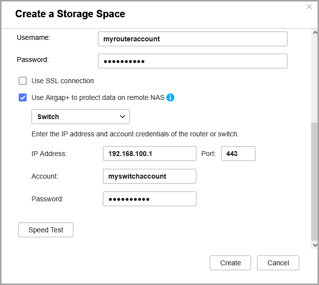
- Click Create.
HBS creates the storage space and adds it to the storage space list.
You should see "Protected by Airgap+" at the top of the storage space entry.
- Create a backup job on the source NAS.
- In HBS, go to Backup & Restore.
- Click Backup Now and then click New backup job.
- Follow the steps in the wizard.
For details, see Creating a backup job.
- After the backup job is created, verify that the Airgap+ link has been established on the switch.
- Log in to QSS or QSS Pro.
- Go to System > Port Management > Airgap+.
- Under Action, click
 .
.
The Paired QNAP Device Details window appears. - Next to Link Status, verify that the status is Up.
You can now run the Airgap+ protected HBS backup job on the source NAS.
Advanced Airgap+
In a switch-based advanced Airgap+ configuration, the source NAS, backup NAS, and bridge NAS all connect to the same isolated switch. The source NAS remains connected to the public network, while the bridge and backup NAS devices stay within the private network through the switch.
Within this secure segment, only the bridge NAS is allowed to communicate with both the source NAS and backup NAS, and only when it is actively running HBS tasks. Since all backup and synchronization workloads are handled by the bridge NAS, the source NAS can conserve resources for other essential operations and services.
How Advanced Airgap+ Works
Under normal circumstances, only the bridge NAS has any allowed communication on the private network segment. The backup NAS remains fully isolated.

When the bridge NAS initiates an Active Sync job in HBS, the switch temporarily permits data transfer from the source NAS to the bridge NAS. During this time, the backup NAS remains isolated.
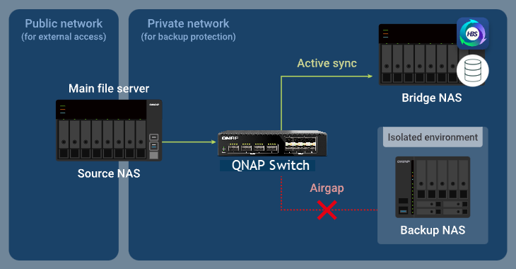
After the sync job finishes, the bridge NAS runs a Backup job. The switch then allows data to flow from the bridge NAS to the backup NAS, while blocking the source NAS from accessing the private network.

Advanced Airgap+ Setup Instructions
To deploy an advanced Airgap+ environment using a switch, you must configure the Airgap+ switch and all NAS devices (source, bridge, and backup) before creating HBS jobs. Once the network and device settings are complete, you can begin building the synchronized and backup workflows in HBS.
A. Configure the switch
- Connect the source, bridge, and backup NAS devices directly to the Airgap+ switch to create a private network.Important
It is recommended to configure a static IP address for the backup NAS to ensure that the Airgap+ settings on all devices remain valid over time.
To configure a static IP address for the backup NAS network adapter that is connected to the switch, see one of the following:
- "Configuring IPv4 settings" in the QTS User Guide or QuTS hero User Guide
- "Configuring IPv6 settings" in the QTS User Guide or QuTS hero User Guide
- Obtain the IP address of your backup and source NAS in the private network.
- Open Qfinder Pro.
- Identify the source NAS device.
- Copy the source NAS IP address.Note
- The NAS may have more than one IP address listed. Copy the IP address that is in the same IP range as the switch.
In our example, the IP address is192.168.100.100. - Use this IP address in step B-2c and D-1e.
- The NAS may have more than one IP address listed. Copy the IP address that is in the same IP range as the switch.
- Identify and copy the backup NAS IP address.Note
- The NAS may have more than one IP address listed. Copy the IP address that is in the same IP range as the switch.
In our example, the IP address is192.168.102.100. - Use this IP address in step B-3c and D-2e.
- The NAS may have more than one IP address listed. Copy the IP address that is in the same IP range as the switch.
- Obtain the LAN port IP addresses and subnet masks on the Airgap+ switch for ports connected to the source and backup NAS devices.
- In QSS, go to System >IP Configuration > IPv4 Interface Settings
- Identify the IPv4 interface addresses that's connected to the NAS.
- Under IP Address, copy the IPv4 address for the LAN port connected to the source NAS.NoteUse the last octet of the IP address in step B-2e. In our example, the last octet of the IP address
192.168.100.1is1. - Copy the subnet mask for the LAN port connected to the source NAS.NoteSpecify the subnet mask in step B-2d.
In our example, the subnet mask is/24. - Copy the IP address for the LAN port connected to the backup NAS.NoteUse the last octet of the IP address in step B-3e.
In our example, the last octet of the IP address192.168.102.1is1. - Copy the subnet mask for the LAN port connected to the backup NAS.NoteSpecify the subnet mask in step B-3d.
In our example, the subnet mask is/24.
B. Configure the bridge NAS
- Identify the bridge NAS adapter that is connected to the Airgap+ switch.
- On the bridge NAS, open Network & Virtual Switch.
- Go to Network > Interfaces.
- Identify the adapter that is connected to the Airgap+ switch.NoteUse this adapter in steps B-2f and B-3f.
In our example, adapter 5 is connected to the Airgap+ switch. - Copy the IP address of the adapter.NoteUse the first three octets of the IP address in steps B-2e and B-3e.
In our example, the first three octets of the IP address192.168.104.100are192.168.104.
- Create a static route rule on the bridge NAS for connecting to the source NAS.
- On the bridge NAS, go to Network & Virtual Switch > Network > Route.
- Under Static Route, click Add.
The Static Route (IPv4) window opens. - Next to Destination, specify the IP address of the source NAS (see step A-2c).
- Next to Netmask, specify the subnet mask of the switch LAN port that is connected to the source NAS (see step A-3d).
- Next to Gateway, specify the first three octets of the IP address for the bridge NAS adapter that is connected to the switch (see step B-1d), followed by the last octet of the IP address for the switch LAN port that is connected to the source NAS (see step A-3c).NoteIn our example:
- Step B-1d provides the first three octets of the IP address (
192.168.104). - Step A-3c provides the IP address of the switch LAN port connected to the source NAS. Use the last octet from this address (
1).
Join the two to obtain
192.168.104.1. Enter this address in the Gateway field.
Also use this address in step D-1j. - Step B-1d provides the first three octets of the IP address (
- Next to Interface, select the bridge NAS adapter that is connected to the switch (see step B-1c).
- Click Apply.
Network & Virtual Switch adds the static route rule.
- Create a static route rule on the bridge NAS for connecting to the backup NAS.
- On the bridge NAS, remain in Network & Virtual Switch > Network > Route.
- Under Static Route, click Add.
The Static Route (IPv4) window opens. - Next to Destination, specify the IP address of the backup NAS (see step A-2d).
- Next to Netmask, specify the subnet mask of the switch LAN port that is connected to the backup NAS (see step A-3f).
- Next to Gateway, specify the first three octets of the IP address for the bridge NAS adapter that is connected to the switch (see step B-1d), followed by the last octet of the IP address for the switch LAN port that is connected to the backup NAS (see step A-3e).NoteIn our example:
- Step B-1d provides the first three octets of the IP address (
192.168.104). - For this route, use the last octet (
1) of the IP address of the switch LAN port connected to the backup NAS (see step A-3e).
Join the two to obtain
192.168.104.1. Enter this address in the Gateway field.
Also use this address in step D-2j. - Step B-1d provides the first three octets of the IP address (
- Next to Interface, select the bridge NAS adapter that is connected to the switch (see step B-1c).
- Click Apply.
Network & Virtual Switch adds the static route rule.
C. Configure the source and backup NAS devices
- Enable the RTRR server on the source NAS.
This allows HBS jobs on the bridge NAS to use the source NAS as a sync source.- On the source NAS, open HBS.
- Go to Services > Remote NAS (RTRR Server).
- Next to Status, click the toggle button to enable the RTRR server.
- Configure the RTRR server settings.
For details, see Configuring the RTRR server.Note- Copy the port number specified on this page and enter it in step D-1f.
- Remember the account access method and credentials configured here and use them in steps D-1g and D-1h.
- Click Apply.
HBS enables the RTRR server on the source NAS.
- Enable the RTRR server on the backup NAS.
This allows HBS jobs on the bridge NAS to use the backup NAS as a backup destination.- On the backup NAS, open HBS.
- Go to Services > Remote NAS (RTRR Server).
- Next to Status, click the toggle button to enable the RTRR server.
- Configure the RTRR server settings.
For details, see Configuring the RTRR server.Note- Copy the port number specified on this page and enter it in step D-2f.
- Remember the account access method and credentials configured here and use them in steps D-2g and D-2h.
- Click Apply.
HBS enables the RTRR server on the backup NAS.
D. Create HBS jobs on the bridge NAS
- In HBS on the bridge NAS, create a storage space for the source NAS.
This allows you to save the connection settings of the source NAS and enable an Airgap+ connection between the source NAS and the bridge NAS.- On the bridge NAS, open HBS.
- Go to Storage Spaces.
- Click Create, and then click Remote NAS.
The Create a Storage Space window opens. - Enter a name to identify the source NAS.
- Enter the source NAS IP address (see step A-2c).
- Enter the source NAS RTRR server port number (see step C-1d).
- Select an account access method you configured in the RTRR server settings on the source NAS (see step C-1d).
- Enter the credentials for the account access method (see step C-1d).
- Select Use Airgap+ to protect data on remote NAS.
- Select Switch as the Airgap+ device.
- Enter the gateway IP address from the static route rule on the bridge NAS for connecting to the source NAS (see step B-2e).
- Enter the port number.
- Enter the switch management account credentials.
- Click Create.
HBS creates the storage space and adds it to the storage space list.
- In HBS on the bridge NAS, create a storage space for the backup NAS.
This allows you to save the connection settings of the backup NAS and enable an Airgap+ connection between the bridge NAS and the backup NAS.- On the bridge NAS, stay in HBS.
- Go to Storage Spaces.
- Click Create, and then click Remote NAS.
The Create a Storage Space window opens. - Enter a name to identify the backup NAS.
- Enter the backup NAS IP address (see step A-2d).
- Enter the backup NAS RTRR server port number (see step C-2d).
- Select an account access method you configured in the RTRR server settings on the backup NAS (see step C-2d).
- Enter the credentials for the account access method (see step C-2d).
- Select Use Airgap+ to protect data on remote NAS.
- Enter the gateway IP address from the static route rule on the bridge NAS for connecting to the backup NAS (see step B-3e).
- Enter the switch management account credentials.
- Click Create.
HBS creates the storage space and adds it to the storage space list.
After both storage spaces are created, you should see "Protected by Airgap+" at the top of the storage space entries in HBS > Storage Spaces.
- Create an active sync job on the bridge NAS to transfer backup data from the source NAS to the bridge NAS.
- On the bridge NAS, go to HBS > Sync.
- Click Sync Now and then click Active Sync Job.
- Follow the steps in the wizard.
For details, see Creating an active sync job.
- Create a backup job on the bridge NAS to transfer the backup data to the backup NAS.
- On the bridge NAS, go to HBS > Backup & Restore.
- Click Backup Now and then click New backup job.
- Follow the wizard to select the source and destination folders.ImportantMake sure the source folder in this backup job is the same as the destination folder in the active sync job you just created.
- On the Schedule page, select Run after job, and then select the active sync job you just created.
This allows the backup job to automatically run every time the active sync job finishes, completing the backup data transfer to your backup NAS. - Follow the remaining steps in the wizard.
For details, see Creating a backup job.
- After the active sync job and backup job are created, verify that the Airgap+ links have been established on the switch.
- Log in to QSS or QSS Pro.
- Go to System > Port Management > Airgap+.
- Under Action, click .
The Paired QNAP Device Details window appears. - Next to Link Status, verify that the status is Up.
- You can now run the HBS active sync job on the bridge NAS to transfer the data you want to back up.
After the active sync job finishes transferring the backup data from the source NAS to the bridge NAS, the backup job will automatically run and transfer the backup data from the bridge NAS to its final destination, the backup NAS. The entire process is now protected by Airgap+.


