Applicable Products
Hardware
- QSW-M7308R-4X
- QSW-M3224-24T
Software
Details
Multichassis link aggregation (MC-LAG) allows two switches to operate as a single logical switch. It uses a peer link between the switches to coordinate traffic and link aggregation groups (LAGs) to combine multiple physical ports for redundancy and load sharing.
For NAS devices, MC-LAG enables connections to either switch while maintaining a single aggregated link. This provides redundancy (connections remain active if one switch fails), higher bandwidth (multiple NAS ports aggregated across switches), and load balancing across all member ports, ensuring resilient, high-performance storage access.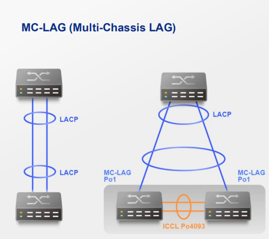
Procedure
A. Configure LAG groups
Important
Ensure that you configure the LAG before connecting cables to the switch to avoid creating a data loop.
- Log in to the switch system.
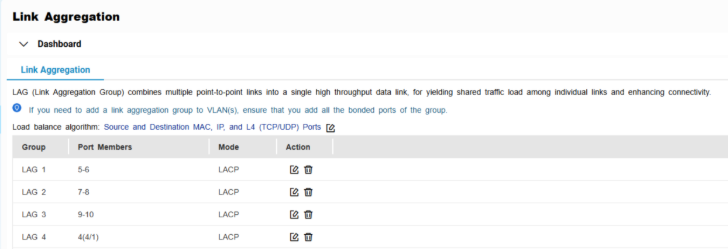
- Go to L2 Features > Link Aggregation.
- Identify a group.
- Click
 .
.
The Edit Group window appears. - Configure the group settings.
| Setting | Description |
|---|
| Mode | Controls the link aggregation mode for the group.
Select LACP to ensure automatic negotiation and failover for stable MC-LAG operation. |
| Port Configuration | Specifies which ports are included in the group Note Ensure that you configure the same settings for all the member ports in a LAG. |
- Click Save.
Note
Make sure the same LAGs are configured on both switches.
B. Configure MC-LAG settings
- Log in to the switch system.
- Click MC-LAG.
- Click Settings.
The MC-LAG Settings window appears.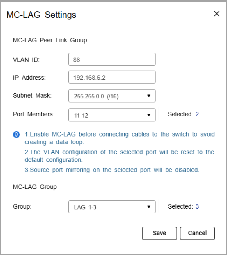
- Specify the VLAN ID.
Use the same VLAN on both switches. This VLAN is reserved for the peer link. - Specify the IP address for inter-chassis control protocol (ICCP) communication.
Assign the peer link IP address within the same subnet as the other switch, using a VLAN other than VLAN 1. - Specify the IP subnet mask.
The subnet mask must match on both switches. - Select one or more member ports.
Assign at least two ports for redundancy. - Select one or more link aggregation groups (MC-LAG group).
Note
Use the LAGs created earlier, and ensure the same LAG IDs are configured on both switches.
- Click Save.
The switch saves the MC-LAG configuration. - On the MC-LAG page, click Enable.
The switch enables MC-LAG. - Configure the MC-LAG settings on the peer switch.
- Reboot both switches.
C. Verify configuration
- Check MC-LAG status in the settings page.
- Verify the peer link and member ports are active.
Connection Guide
- Enable port trunking on the QNAP NAS.
For details, see "Configuring port trunking settings" in the QTS User Guide or QuTS hero User Guide. - Connect each NAS network port to switch ports that are members of the same LAG ID on both switches.
If the NAS trunk group is assigned to LAG 1, NAS port 1 can connect to a LAG 1 member port on switch A, and NAS port 2 can connect to a LAG 1 member port on switch B.Note
The NAS ports in the trunk can either connect to the same switch or be split across the two MC-LAG peer switches. In both cases, the ports must belong to the same LAG ID
- Verify the connection.
- On the NAS, confirm that the port trunking group shows all member ports as active.
- On the switches, check that the assigned LAG connection is active and monitoring traffic.
Example Topology
Two switches are configured in an MC-LAG cluster, allowing them to operate as a single logical switch. The switches coordinate traffic over a peer link and use link aggregation groups (LAGs) to combine multiple physical ports for redundancy and load sharing.
Multiple NAS devices can connect to the cluster using link aggregation. Each NAS can distribute its network ports across both switches. For example, one NAS port can connect to switch A and another port can connect to switch B, while still maintaining a single aggregated connection.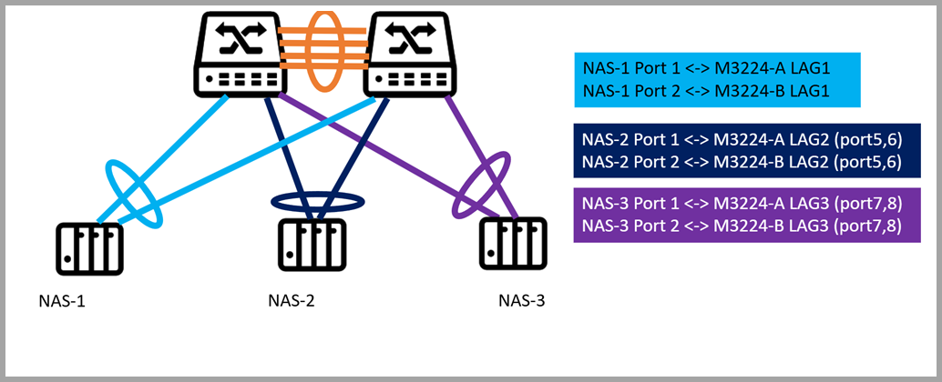
Each NAS is connected to two switches (QSW-M3224-A and QSW-M3224-B) using port trunking. The connections are grouped via dynamic link aggregation (LAG) as follows:
- NAS-1 -> LAG1: Ports 1 and 2 on both switches
- NAS-2 -> LAG2: Ports 5 and 6 on both switches
- NAS-3 -> LAG3: Ports 7 and 8 on both switches
Note
"A" and "B" indicate the respective switches. Each LAG spans both switches to provide redundancy and load balancing.
From the network perspective, the MC-LAG cluster ensures that if one switch or a single port fails, the NAS continues to communicate through the remaining switch, providing uninterrupted access to storage. Traffic is automatically load balanced across all LAG member ports, maximizing throughput and avoiding bottlenecks.
For NAS users, this configuration simplifies network management, improves performance, and provides resilient, high-availability storage access without requiring complex failover setup.
Further Reading
適用產品
硬體
- QSW-M7308R-4X
- QSW-M3224-24T
軟體
詳細資訊
多機箱鏈路聚合 (MC-LAG) 允許兩個交換機作為單一邏輯交換機運作。它使用交換機之間的對等鏈路來協調流量,並使用鏈路聚合群組 (LAG) 來結合多個實體埠以提供備援和負載共享。
對於 NAS 設備,MC-LAG 允許連接到任一交換機,同時維持單一聚合鏈路。這提供了備援(如果一個交換機故障,連接仍然保持活躍)、更高的頻寬(多個 NAS 埠跨交換機聚合),以及負載平衡在所有成員埠之間,確保高效能的儲存空間存取。
程式
A. 配置 LAG 群組
重要
確保在連線電纜到交換機之前配置 LAG,以避免建立資料迴路。
- 登入交換機系統。
- 前往L2 功能>鏈路聚合。
- 識別一個群組。
- 按一下.
編輯群組視窗隨即顯示。 - 點選.
| 設定群組設定。 | 設定 |
|---|
| 說明 | 模式 |
| 確定為所有成員埠配置相同的設定。 | 點選。
編輯群組視窗隨即顯示。點選 . 選擇 MC-LAG以確保自動協商和容錯移轉以穩定 MC-LAG 運行。 埠配置 |
- 說明哪些埠包含在 LAG 群組中
注意
- 確保為 LAG 中的所有成員埠配置相同的設定。
- 點選.
.注意確保兩個交換機上配置了相同的 LAG。
B. 配置 MC-LAG登入交換機系統。 - 點選
- 指定 VLAN ID。
在兩個交換機上使用相同的 VLAN。此 VLAN 保留用於對等連接。 - 指定用於機箱間控制協議 (ICCP) 通訊的 IP 位址。
將對等連接 IP 位址分配在與另一個交換機相同的子網中,使用除 VLAN 1 以外的 VLAN。 - 指定 IP 子網遮罩。
子網遮罩必須在兩個交換機上匹配。 - 選擇一個或多個成員埠。
分配至少兩個埠以確保備援。 - 選擇一個或多個鏈路聚合組 (MC-LAG 組)。
注意
使用先前建立的 LAG,並確保在兩個交換機上配置相同的 LAG ID。
- 按一下儲存。
交換機儲存 MC-LAG 設定。 - 在 MC-LAG 頁面上,按一下啟用。
交換機啟用 MC-LAG。 - 在對等交換機上配置 MC-LAG 設定。
- 重新啟動兩個交換機。
C. 驗證設定
- 在設定頁面檢查 MC-LAG 狀態。
- 確認對等連線和成員埠處於啟用狀態。
連線指南
- 在 QNAP NAS 上啟用 Port Trunking。
如需詳細資訊,請參見「配置 Port Trunking 設定」於QTS 使用者指南或QuTS hero 使用者指南。 - 將每個 NAS 網路埠連接到兩個交換機上屬於相同 LAG ID 的交換機埠。
如果 NAS 中繼組分配給 LAG 1,則 NAS 埠 1 可以連接到交換機 A 上的 LAG 1 成員埠,而 NAS 埠 2 可以連接到交換機 B 上的 LAG 1 成員埠。注意
中繼中的 NAS 埠可以連接到同一交換機或分佈在兩個 MC-LAG 對等交換機上。在這兩種情況下,埠必須屬於相同的 LAG ID
- 驗證連線。
- 在 NAS 上,確認 Port Trunking 組顯示所有成員埠為啟用狀態。
- 在交換機上,檢查分配的 LAG 連線是否啟用並監控流量。
範例拓撲
兩個交換器配置在 MC-LAG 叢集中,使它們能夠作為單一邏輯交換器運作。這些交換器透過對等連結協調流量,並使用連結聚合群組 (LAG) 結合多個實體埠以提供備援和負載共享。
多台 NAS 設備可以使用連結聚合連接到叢集。每台 NAS 可以將其網路埠分配到兩個交換器上。例如,一個 NAS 埠可以連接到交換器 A,另一個埠可以連接到交換器 B,同時仍維持單一聚合連接。
每台 NAS 使用 Port Trunking 連接到兩個交換器 (QSW-M3224-A 和 QSW-M3224-B)。這些連接透過動態連結聚合 (LAG) 分組如下:
- NAS-1 -> LAG1:兩個交換器上的埠 1 和 2
- NAS-2 -> LAG2:兩個交換器上的埠 5 和 6
- NAS-3 -> LAG3:兩個交換器上的埠 7 和 8
註
「A」和「B」表示各自的交換器。每個 LAG 跨越兩個交換器以提供備援和負載平衡。
從網路的角度來看,MC-LAG 叢集確保如果一個交換器或單一埠故障,NAS 仍能透過剩餘的交換器進行通訊,提供不間斷的儲存空間存取。流量會自動在所有 LAG 成員埠之間負載平衡,最大化輸送量並避免瓶頸。
對於 NAS 使用者來說,這種配置簡化了網路管理,提升了效能,並提供了彈性、高可用性的儲存空間存取,而不需要複雜的容錯移轉設置。
進一步閱讀


