How to configure MC-LAG settings on QNAP switches for high availability?
Applicable Products
Hardware
- QSW-M7308R-4X
- QSW-M3224-24T
Software
- QSS Pro 4.1 and later
Details
Multichassis link aggregation (MC-LAG) allows two switches to operate as a single logical switch. It uses a peer link between the switches to coordinate traffic and link aggregation groups (LAGs) to combine multiple physical ports for redundancy and load sharing.
For NAS devices, MC-LAG enables connections to either switch while maintaining a single aggregated link. This provides redundancy (connections remain active if one switch fails), higher bandwidth (multiple NAS ports aggregated across switches), and load balancing across all member ports, ensuring resilient, high-performance storage access.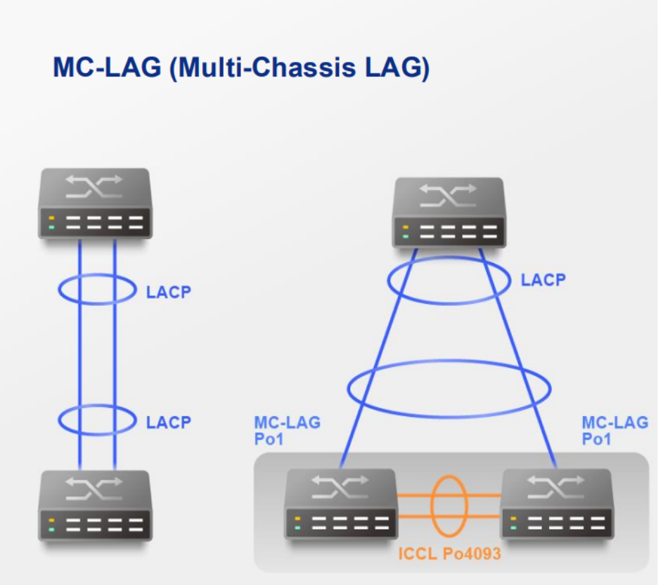
Procedure
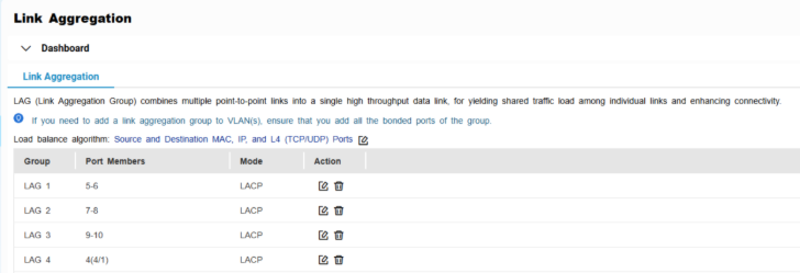
A. Configure LAG groups
- Log in to the switch system.
- Go to L2 Features > Link Aggregation.
- Identify a group.
- Click
 .
.
The Edit Group window appears. - Configure the group settings.
Setting Description Mode Controls the link aggregation mode for the group.
Select LACP to ensure automatic negotiation and failover for stable MC-LAG operation.Port Configuration Specifies which ports are included in the group NoteEnsure that you configure the same settings for all the member ports in a LAG. - Click Save.NoteMake sure the same LAGs are configured on both switches.
B. Configure MC-LAG settings
- Log in to the switch system.
- Click MC-LAG.
- Click Settings.
The MC-LAG Settings window appears.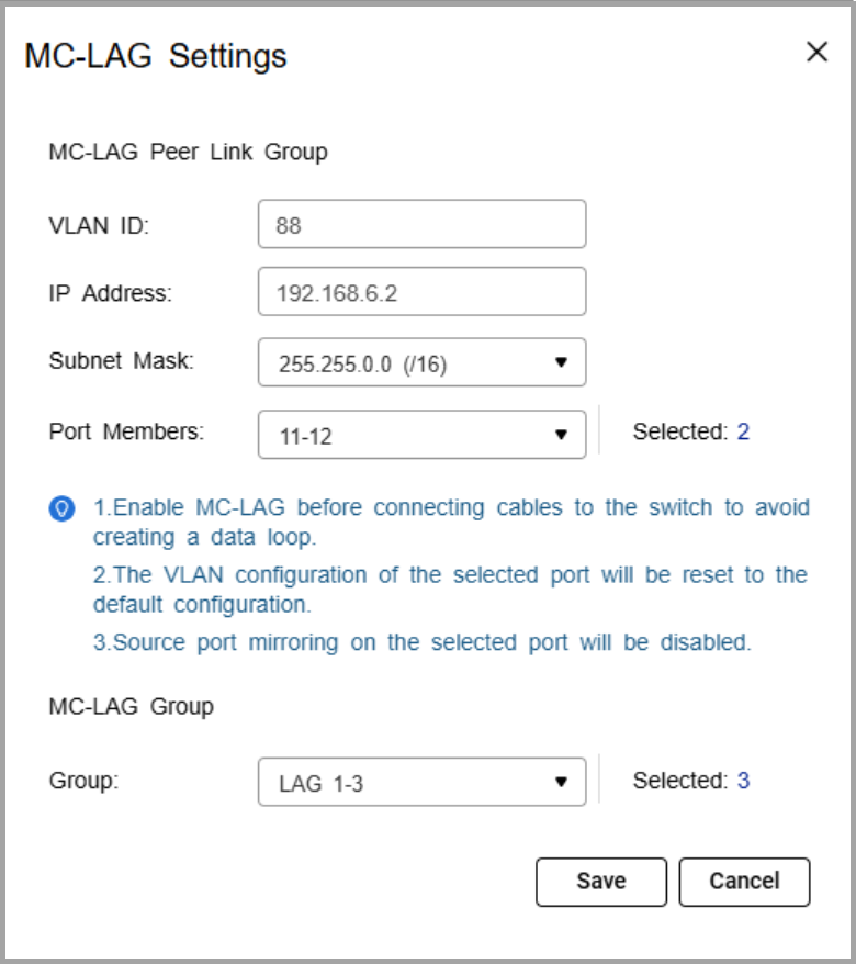
- Specify the VLAN ID.
Use the same VLAN on both switches. This VLAN is reserved for the peer link. - Specify the IP address for inter-chassis control protocol (ICCP) communication.
Assign the peer link IP address within the same subnet as the other switch, using a VLAN other than VLAN 1. - Specify the IP subnet mask.
The subnet mask must match on both switches. - Select one or more member ports.
Assign at least two ports for redundancy. - Select one or more link aggregation groups (MC-LAG group).NoteUse the LAGs created earlier, and ensure the same LAG IDs are configured on both switches.
- Click Save.
The switch saves the MC-LAG configuration. - On the MC-LAG page, click Enable.
The switch enables MC-LAG. - Configure the MC-LAG settings on the peer switch.
- Reboot both switches.
C. Verify configuration
- Check MC-LAG status in the settings page.
- Verify the peer link and member ports are active.
Connection Guide
- Enable port trunking on the QNAP NAS.
For details, see "Configuring port trunking settings" in the QTS User Guide or QuTS hero User Guide. - Connect each NAS network port to switch ports that are members of the same LAG ID on both switches.
If the NAS trunk group is assigned to LAG 1, NAS port 1 can connect to a LAG 1 member port on switch A, and NAS port 2 can connect to a LAG 1 member port on switch B.NoteThe NAS ports in the trunk can either connect to the same switch or be split across the two MC-LAG peer switches. In both cases, the ports must belong to the same LAG ID - Verify the connection.
- On the NAS, confirm that the port trunking group shows all member ports as active.
- On the switches, check that the assigned LAG connection is active and monitoring traffic.
Example Topology
Two switches are configured in an MC-LAG cluster, allowing them to operate as a single logical switch. The switches coordinate traffic over a peer link and use link aggregation groups (LAGs) to combine multiple physical ports for redundancy and load sharing.
Multiple NAS devices can connect to the cluster using link aggregation. Each NAS can distribute its network ports across both switches. For example, one NAS port can connect to switch A and another port can connect to switch B, while still maintaining a single aggregated connection.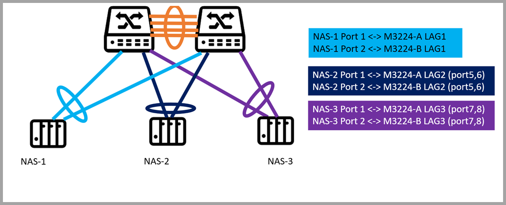
Each NAS is connected to two switches (QSW-M3224-A and QSW-M3224-B) using port trunking. The connections are grouped via dynamic link aggregation (LAG) as follows:
- NAS-1 -> LAG1: Ports 1 and 2 on both switches
- NAS-2 -> LAG2: Ports 5 and 6 on both switches
- NAS-3 -> LAG3: Ports 7 and 8 on both switches
From the network perspective, the MC-LAG cluster ensures that if one switch or a single port fails, the NAS continues to communicate through the remaining switch, providing uninterrupted access to storage. Traffic is automatically load balanced across all LAG member ports, maximizing throughput and avoiding bottlenecks.
For NAS users, this configuration simplifies network management, improves performance, and provides resilient, high-availability storage access without requiring complex failover setup.


