Applicable Products
Hardware
- QSW-M7308R-4X
- QSW-M3224-24T
Software
Details
Multichassis link aggregation (MC-LAG) allows two switches to operate as a single logical switch. It uses a peer link between the switches to coordinate traffic and link aggregation groups (LAGs) to combine multiple physical ports for redundancy and load sharing.
For NAS devices, MC-LAG enables connections to either switch while maintaining a single aggregated link. This provides redundancy (connections remain active if one switch fails), higher bandwidth (multiple NAS ports aggregated across switches), and load balancing across all member ports, ensuring resilient, high-performance storage access.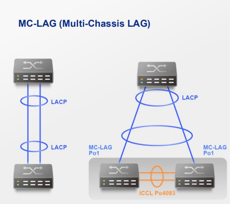
Procedure
A. Configure LAG groups
Important
Ensure that you configure the LAG before connecting cables to the switch to avoid creating a data loop.
- Log in to the switch system.
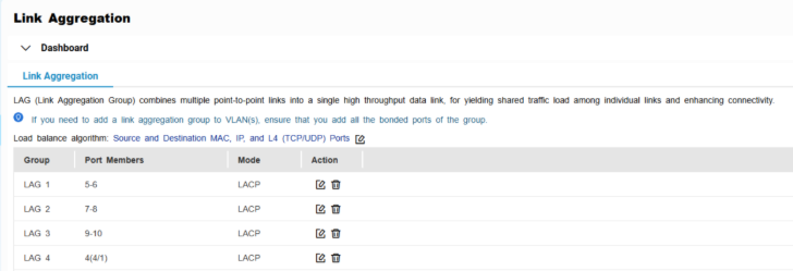
- Go to L2 Features > Link Aggregation.
- Identify a group.
- Click
 .
.
The Edit Group window appears. - Configure the group settings.
| Setting | Description |
|---|
| Mode | Controls the link aggregation mode for the group.
Select LACP to ensure automatic negotiation and failover for stable MC-LAG operation. |
| Port Configuration | Specifies which ports are included in the group Note Ensure that you configure the same settings for all the member ports in a LAG. |
- Click Save.
Note
Make sure the same LAGs are configured on both switches.
B. Configure MC-LAG settings
- Log in to the switch system.
- Click MC-LAG.
- Click Settings.
The MC-LAG Settings window appears.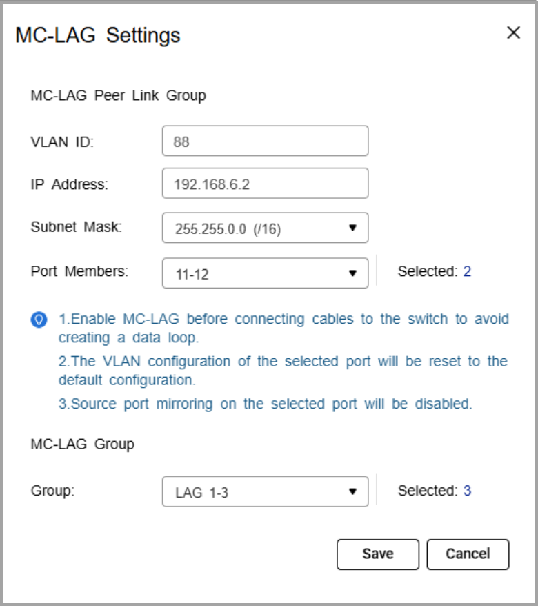
- Specify the VLAN ID.
Use the same VLAN on both switches. This VLAN is reserved for the peer link. - Specify the IP address for inter-chassis control protocol (ICCP) communication.
Assign the peer link IP address within the same subnet as the other switch, using a VLAN other than VLAN 1. - Specify the IP subnet mask.
The subnet mask must match on both switches. - Select one or more member ports.
Assign at least two ports for redundancy. - Select one or more link aggregation groups (MC-LAG group).
Note
Use the LAGs created earlier, and ensure the same LAG IDs are configured on both switches.
- Click Save.
The switch saves the MC-LAG configuration. - On the MC-LAG page, click Enable.
The switch enables MC-LAG. - Configure the MC-LAG settings on the peer switch.
- Reboot both switches.
C. Verify configuration
- Check MC-LAG status in the settings page.
- Verify the peer link and member ports are active.
Connection Guide
- Enable port trunking on the QNAP NAS.
For details, see "Configuring port trunking settings" in the QTS User Guide or QuTS hero User Guide. - Connect each NAS network port to switch ports that are members of the same LAG ID on both switches.
If the NAS trunk group is assigned to LAG 1, NAS port 1 can connect to a LAG 1 member port on switch A, and NAS port 2 can connect to a LAG 1 member port on switch B.Note
The NAS ports in the trunk can either connect to the same switch or be split across the two MC-LAG peer switches. In both cases, the ports must belong to the same LAG ID
- Verify the connection.
- On the NAS, confirm that the port trunking group shows all member ports as active.
- On the switches, check that the assigned LAG connection is active and monitoring traffic.
Example Topology
Two switches are configured in an MC-LAG cluster, allowing them to operate as a single logical switch. The switches coordinate traffic over a peer link and use link aggregation groups (LAGs) to combine multiple physical ports for redundancy and load sharing.
Multiple NAS devices can connect to the cluster using link aggregation. Each NAS can distribute its network ports across both switches. For example, one NAS port can connect to switch A and another port can connect to switch B, while still maintaining a single aggregated connection.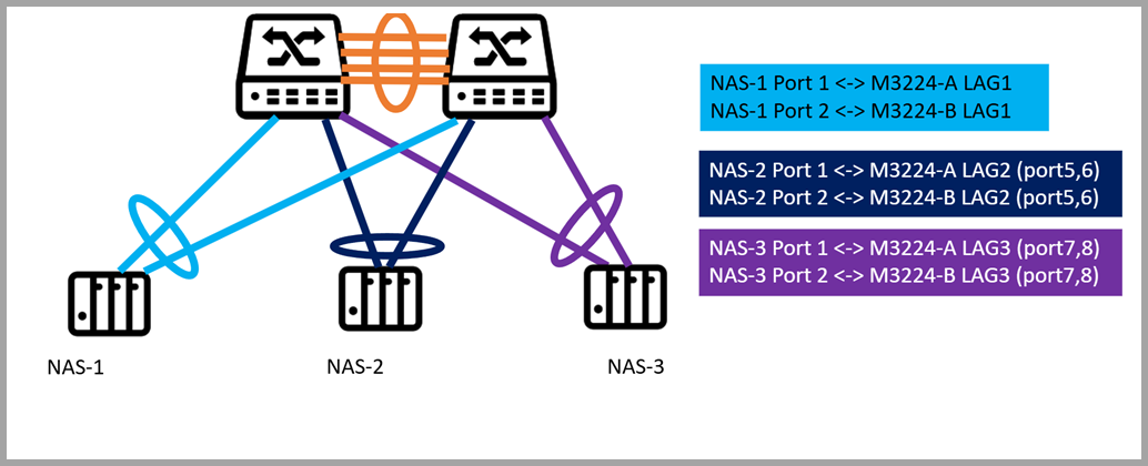
Each NAS is connected to two switches (QSW-M3224-A and QSW-M3224-B) using port trunking. The connections are grouped via dynamic link aggregation (LAG) as follows:
- NAS-1 -> LAG1: Ports 1 and 2 on both switches
- NAS-2 -> LAG2: Ports 5 and 6 on both switches
- NAS-3 -> LAG3: Ports 7 and 8 on both switches
Note
"A" and "B" indicate the respective switches. Each LAG spans both switches to provide redundancy and load balancing.
From the network perspective, the MC-LAG cluster ensures that if one switch or a single port fails, the NAS continues to communicate through the remaining switch, providing uninterrupted access to storage. Traffic is automatically load balanced across all LAG member ports, maximizing throughput and avoiding bottlenecks.
For NAS users, this configuration simplifies network management, improves performance, and provides resilient, high-availability storage access without requiring complex failover setup.
Further Reading
적용되는 제품
하드웨어
- QSW-M7308R-4X
- QSW-M3224-24T
소프트웨어
상세 정보
멀티섀시 링크 집계(MC-LAG)는 두 스위치를 단일 논리 스위치로 작동할 수 있게 합니다. 스위치 간의 피어 링크를 사용하여 트래픽을 조정하고 링크 집계 그룹(LAG)을 사용하여 여러 물리적 포트를 결합하여 이중화 및 부하 분산을 제공합니다.
NAS 장치의 경우, MC-LAG는 단일 집계 링크를 유지하면서 어느 스위치에나 연결할 수 있게 합니다. 이는 이중화(한 스위치가 실패해도 연결이 유지됨), 더 높은 대역폭(스위치 간에 집계된 여러 NAS 포트), 모든 멤버 포트에 걸친로드 밸런싱를 제공하여 탄력적이고 고성능의스토리지액세스를 보장합니다.
절차
A. LAG 그룹 구성
중요
데이터 루프 생성을 피하기 위해서 케이블을 스위치에 연결하기 전에 LAG를 구성했는지 확인합니다.
- 스위치 시스템에 로그인합니다.
- 이동합니다L2 기능>링크 집계.
- 그룹을 식별합니다.
- 을 클릭합니다.
그룹 편집창이 나타납니다. - 그룹 설정을 구성합니다.
| 설정 | 설명 |
|---|
| 모드 | 그룹의 링크 집계 모드를 제어합니다.
LACP를 선택하여 자동 협상 및 안정적인 MC-LAG 작동을 위한장애 조치를 보장합니다. |
| 포트 구성 | 그룹에 포함될 포트를 지정합니다. 참고 LAG의 모든 멤버 포트에 대해 동일한 설정을 구성하도록 합니다. |
- 저장을 클릭합니다.
참고
양쪽 스위치에 동일한 LAG가 구성되어 있는지 확인하십시오.
B. MC-LAG 설정 구성
- 스위치 시스템에 로그인합니다.
- 클릭합니다MC-LAG.
- 설정을 클릭합니다.
MC-LAG 설정창이 나타납니다. - VLAN ID를 지정합니다.
양쪽 스위치에서 동일한 VLAN을 사용합니다. 이 VLAN은 피어 링크에 예약되어 있습니다. - 섀시간 제어 프로토콜(ICCP) 통신을 위한 IP 주소를 지정합니다.
피어 링크 IP 주소를 다른 스위치와 동일한 서브넷 내에서 할당하고, VLAN 1이 아닌 VLAN을 사용합니다. - IP 서브넷 마스크를 지정합니다.
서브넷 마스크는 양쪽 스위치에서 일치해야 합니다. - 하나 이상의 구성원 포트를 선택합니다.
이중화를 위해 최소 두 개의 포트를 할당합니다. - 하나 이상의 링크 집계 그룹(MC-LAG 그룹)을 선택합니다.
참고
이전에 생성된 LAG를 사용하고, 양쪽 스위치에서 동일한 LAG ID가 구성되었는지 확인합니다.
- 저장을 클릭합니다.
스위치가 MC-LAG 구성을 저장합니다. - MC-LAG 페이지에서활성화를 클릭합니다.
스위치가 MC-LAG를 활성화합니다. - 피어 스위치에서 MC-LAG 설정을 구성합니다.
- 양쪽 스위치를 재부팅합니다.
C. 구성 확인
- 설정 페이지에서 MC-LAG 상태를 확인합니다.
- 피어 링크와 구성원 포트가 활성 상태인지 확인합니다.
연결 가이드
- QNAP NAS에서포트 트렁킹을 활성화합니다.
자세한 내용은QTS 사용 설명서또는QuTS hero 사용 설명서의 "포트 트렁킹설정 구성"을 참조하십시오. - 각 NAS 네트워크 포트를 양쪽 스위치에서 동일한 LAG ID의 구성원인 스위치 포트에 연결합니다.
NAS 트렁크 그룹이 LAG 1에 할당된 경우, NAS 포트 1은 스위치 A의 LAG 1 구성원 포트에 연결할 수 있고, NAS 포트 2는 스위치 B의 LAG 1 구성원 포트에 연결할 수 있습니다.참고
트렁크의 NAS 포트는 동일한 스위치에 연결하거나 두 MC-LAG 피어 스위치에 분할될 수 있습니다. 두 경우 모두 포트는 동일한 LAG ID에 속해야 합니다
- 연결을 확인합니다.
- NAS에서포트 트렁킹그룹이 모든 구성원 포트를 활성 상태로 표시하는지 확인합니다.
- 스위치에서 할당된 LAG 연결이 활성 상태이며 트래픽을 모니터링하고 있는지 확인합니다.
예제 토폴로지
두 스위치는 MC-LAG 클러스터로 구성되어 단일 논리 스위치로 작동할 수 있습니다. 스위치는 피어 링크를 통해 트래픽을 조정하고 링크 집계 그룹(LAG)을 사용하여 여러 물리적 포트를 결합하여 이중성과 로드 공유를 제공합니다.
여러 NAS 장치는 링크 집계를 사용하여클러스터에 연결할 수 있습니다. 각 NAS는 네트워크 포트를 두 스위치에 걸쳐 분산할 수 있습니다. 예를 들어, 하나의 NAS 포트는 스위치 A에 연결되고 다른 포트는 스위치 B에 연결되며, 여전히 단일 집계 연결을 유지합니다.
각 NAS는포트 트렁킹을 사용하여 두 스위치(QSW-M3224-A 및 QSW-M3224-B)에 연결됩니다. 연결은 다음과 같이 동적 링크 집계(LAG)를 통해 그룹화됩니다:
- NAS-1 -> LAG1: 두 스위치의 포트 1 및 2
- NAS-2 -> LAG2: 두 스위치의 포트 5 및 6
- NAS-3 -> LAG3: 두 스위치의 포트 7 및 8
참고
"A"와 "B"는 각각의 스위치를 나타냅니다. 각 LAG는 이중성과로드 밸런싱을 제공하기 위해 두 스위치에 걸쳐 있습니다.
네트워크 관점에서 MC-LAG 클러스터는 하나의 스위치 또는 단일 포트가 실패하더라도 NAS가 남은 스위치를 통해 계속 통신할 수 있도록 하여스토리지에 대한 중단 없는 액세스를 제공합니다. 트래픽은 모든 LAG 멤버 포트에 걸쳐 자동으로 로드 밸런싱되어처리량을 극대화하고 병목 현상을 방지합니다.
NAS 사용자에게 이 구성은 네트워크 관리를 간소화하고 성능을 향상시키며 복잡한장애 조치설정 없이도 탄력적이고 고가용성의스토리지액세스를 제공합니다.
추가 읽기


