Applicable Products
Hardware
- QSW-M7308R-4X
- QSW-M3224-24T
Software
Details
Multichassis link aggregation (MC-LAG) allows two switches to operate as a single logical switch. It uses a peer link between the switches to coordinate traffic and link aggregation groups (LAGs) to combine multiple physical ports for redundancy and load sharing.
For NAS devices, MC-LAG enables connections to either switch while maintaining a single aggregated link. This provides redundancy (connections remain active if one switch fails), higher bandwidth (multiple NAS ports aggregated across switches), and load balancing across all member ports, ensuring resilient, high-performance storage access.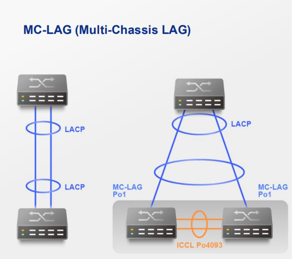
Procedure
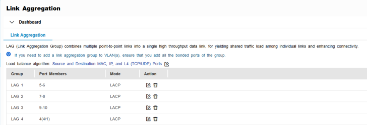
A. Configure LAG groups
Important
Ensure that you configure the LAG before connecting cables to the switch to avoid creating a data loop.
- Log in to the switch system.
- Go to L2 Features > Link Aggregation.
- Identify a group.
- Click
 .
.
The Edit Group window appears. - Configure the group settings.
| Setting | Description |
|---|
| Mode | Controls the link aggregation mode for the group.
Select LACP to ensure automatic negotiation and failover for stable MC-LAG operation. |
| Port Configuration | Specifies which ports are included in the group Note Ensure that you configure the same settings for all the member ports in a LAG. |
- Click Save.
Note
Make sure the same LAGs are configured on both switches.
B. Configure MC-LAG settings
- Log in to the switch system.
- Click MC-LAG.
- Click Settings.
The MC-LAG Settings window appears.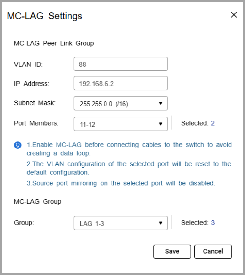
- Specify the VLAN ID.
Use the same VLAN on both switches. This VLAN is reserved for the peer link. - Specify the IP address for inter-chassis control protocol (ICCP) communication.
Assign the peer link IP address within the same subnet as the other switch, using a VLAN other than VLAN 1. - Specify the IP subnet mask.
The subnet mask must match on both switches. - Select one or more member ports.
Assign at least two ports for redundancy. - Select one or more link aggregation groups (MC-LAG group).
Note
Use the LAGs created earlier, and ensure the same LAG IDs are configured on both switches.
- Click Save.
The switch saves the MC-LAG configuration. - On the MC-LAG page, click Enable.
The switch enables MC-LAG. - Configure the MC-LAG settings on the peer switch.
- Reboot both switches.
C. Verify configuration
- Check MC-LAG status in the settings page.
- Verify the peer link and member ports are active.
Connection Guide
- Enable port trunking on the QNAP NAS.
For details, see "Configuring port trunking settings" in the QTS User Guide or QuTS hero User Guide. - Connect each NAS network port to switch ports that are members of the same LAG ID on both switches.
If the NAS trunk group is assigned to LAG 1, NAS port 1 can connect to a LAG 1 member port on switch A, and NAS port 2 can connect to a LAG 1 member port on switch B.Note
The NAS ports in the trunk can either connect to the same switch or be split across the two MC-LAG peer switches. In both cases, the ports must belong to the same LAG ID
- Verify the connection.
- On the NAS, confirm that the port trunking group shows all member ports as active.
- On the switches, check that the assigned LAG connection is active and monitoring traffic.
Example Topology
Two switches are configured in an MC-LAG cluster, allowing them to operate as a single logical switch. The switches coordinate traffic over a peer link and use link aggregation groups (LAGs) to combine multiple physical ports for redundancy and load sharing.
Multiple NAS devices can connect to the cluster using link aggregation. Each NAS can distribute its network ports across both switches. For example, one NAS port can connect to switch A and another port can connect to switch B, while still maintaining a single aggregated connection.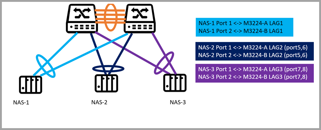
Each NAS is connected to two switches (QSW-M3224-A and QSW-M3224-B) using port trunking. The connections are grouped via dynamic link aggregation (LAG) as follows:
- NAS-1 -> LAG1: Ports 1 and 2 on both switches
- NAS-2 -> LAG2: Ports 5 and 6 on both switches
- NAS-3 -> LAG3: Ports 7 and 8 on both switches
Note
"A" and "B" indicate the respective switches. Each LAG spans both switches to provide redundancy and load balancing.
From the network perspective, the MC-LAG cluster ensures that if one switch or a single port fails, the NAS continues to communicate through the remaining switch, providing uninterrupted access to storage. Traffic is automatically load balanced across all LAG member ports, maximizing throughput and avoiding bottlenecks.
For NAS users, this configuration simplifies network management, improves performance, and provides resilient, high-availability storage access without requiring complex failover setup.
Further Reading
対象製品
ハードウェア
- QSW-M7308R-4X
- QSW-M3224-24T
ソフトウェア
詳細
マルチシャーシリンクアグリゲーション(MC-LAG)は、2 つのスイッチを単一の論理スイッチとして動作させます。スイッチ間のピアリンクを使用してトラフィックを調整し、リンクアグリゲーショングループ(LAG)を使用して複数の物理ポートを組み合わせ、冗長性と負荷分散を実現します。
NAS デバイスに対して、MC-LAG は単一の集約リンクを維持しながら、どちらのスイッチにも接続を可能にします。これにより、冗長性(1 つのスイッチが故障しても接続が維持される)、高帯域幅(複数の NAS ポートがスイッチ間で集約される)、およびすべてのメンバーポートにわたるロードバランシングを提供し、堅牢で高性能なストレージアクセスを保証します。
手順
A. LAG グループを設定する
重要
データループを避けるために、スイッチにケーブルを接続する前に LAG を設定してください。
- スイッチシステムにログインします。
- 移動L2 機能>リンクアグリゲーション
- グループを識別します。
- をクリックします。
グループ編集ウィンドウが表示されます。 - グループ設定を構成します。
| 設定 | 説明 |
|---|
| モード | グループのリンクアグリゲーションモードを制御します。
LACPを選択して自動交渉を確保し、安定した MC-LAG 運用のためのフェイルオーバーを選択します。 |
| ポート設定 | グループに含まれるポートを指定します 注意 LAG のすべてのメンバーポートに同じ設定を構成してください。 |
- 保存をクリックします。
注意
両方のスイッチで同じ LAG が設定されていることを確認してください。
B. MC-LAG 設定を構成する
- スイッチシステムにログインします。
- クリックMC-LAG
- 設定をクリックします。
MC-LAG 設定ウィンドウが表示されます。 - VLAN ID を指定します。
両方のスイッチで同じ VLAN を使用します。この VLAN はピアリンク用に予約されています。 - シャーシ間制御プロトコル (ICCP) 通信のための IP アドレスを指定します。
ピアリンクの IP アドレスを、他のスイッチと同じサブネット内で、VLAN 1 以外の VLAN を使用して割り当てます。 - IP サブネットマスクを指定します。
サブネットマスクは両方のスイッチで一致している必要があります。 - 1 つ以上のメンバーポートを選択します。
冗長性のために少なくとも 2 つのポートを割り当てます。 - 1 つ以上のリンクアグリゲーショングループ (MC-LAG グループ) を選択します。
注意
以前に作成した LAG を使用し、両方のスイッチで同じ LAG ID が設定されていることを確認します。
- 保存をクリックします。
スイッチは MC-LAG 設定を保存します。 - MC-LAG ページで、有効化をクリックします。
スイッチは MC-LAG を有効にします。 - ピアスイッチで MC-LAG 設定を構成します。
- 両方のスイッチを再起動します。
C. 設定の確認
- 設定ページで MC-LAG のステータスを確認します。
- ピアリンクとメンバーポートがアクティブであることを確認します。
接続ガイド
- QNAP NAS でポートトランキングを有効にします。
詳細については、QTS ユーザーガイドまたはQuTS hero ユーザーガイドの「ポートトランキング設定の構成」を参照してください。 - 各 NAS ネットワークポートを、両方のスイッチで同じ LAG ID のメンバーポートに接続します。
NAS トランクグループが LAG 1 に割り当てられている場合、NAS ポート 1 はスイッチ A の LAG 1 メンバーポートに接続でき、NAS ポート 2 はスイッチ B の LAG 1 メンバーポートに接続できます。注意
トランク内の NAS ポートは、同じスイッチに接続するか、2 つの MC-LAG ピアスイッチに分割して接続することができます。いずれの場合も、ポートは同じ LAG ID に属している必要があります
- 接続を確認します。
- NAS で、ポートトランキンググループがすべてのメンバーポートをアクティブとして表示していることを確認します。
- スイッチで、割り当てられた LAG 接続がアクティブでトラフィックを監視していることを確認します。
トポロジーの例
2 つのスイッチが MC-LAG クラスターで構成され、単一の論理スイッチとして動作します。スイッチはピアリンクを介してトラフィックを調整し、リンクアグリゲーショングループ(LAG)を使用して複数の物理ポートを組み合わせ、冗長性と負荷分散を実現します。
複数の NAS デバイスがリンクアグリゲーションを使用してクラスターに接続できます。各 NAS はネットワークポートを両方のスイッチに分散させることができます。例えば、1 つの NAS ポートはスイッチ A に接続し、もう 1 つのポートはスイッチ B に接続しながら、単一の集約接続を維持します。
各 NAS はポートトランキングを使用して 2 つのスイッチ(QSW-M3224- A および QSW-M3224-B)に接続されています。接続は動的リンクアグリゲーション(LAG)を介して次のようにグループ化されています:
- NAS-1 -> LAG1: 両方のスイッチのポート 1 と 2
- NAS-2 -> LAG2: 両方のスイッチのポート 5 と 6
- NAS-3 -> LAG3: 両方のスイッチのポート 7 と 8
注意
「A」と「B」はそれぞれのスイッチを示しています。各 LAG は冗長性とロードバランシングを提供するために両方のスイッチにまたがっています。
ネットワークの観点から、MC-LAG クラスターは、1 つのスイッチまたは単一のポートが故障した場合でも、NAS が残りのスイッチを通じて通信を続け、ストレージへの途切れないアクセスを提供します。トラフィックはすべての LAG メンバーポートに自動的に負荷分散され、スループットを最大化し、ボトルネックを回避します。
NAS ユーザーにとって、この構成はネットワーク管理を簡素化し、パフォーマンスを向上させ、複雑なフェイルオーバー設定を必要とせずに、回復力のある高可用性のストレージアクセスを提供します。
さらに読む


